1500 North Belcher Road, Clearwater, FL 33765 • Tel (727) 447-6140 • Fax (727) 442-5699 • sales@onicon.com
Turbine Flow Meter Manual 05/13 - 0721-1 / 13518 Page 21
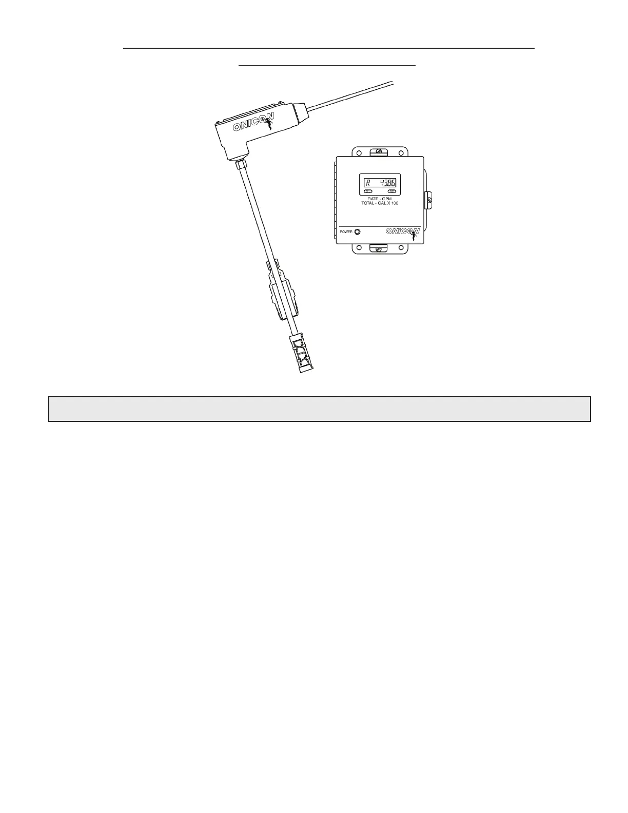
Position
Clamping Nut
Leave sufficient slack in conduit
and cable to allow the meter to be
removed without disconnecting wires.
4.1 HELPFUL HINTS FOR START-UP AND COMMISSIONING
Step-by-step procedures and companion worksheets are located on the next four pages. Please
read all installation instructions carefully before proceeding with start-up and commissioning.
Please read these helpful hints before proceeding with the start-up and commissioning procedure
on the next page.
1. ONICON ow meters are individually calibrated for a particular application. Be sure to
verify the pipe size and location.
2. The electronic sensing systems will not work in air. Blowing on the turbine(s) will
not produce a signal. You can test the meter by holding the turbines under a faucet or
carefully moving it back and forth in a bucket of water.
3. When measuring analog output signals, remember that current (mA) must be measured
in series, while voltage is measured in parallel. If the 4-20 mA signal is already
connected to a control system, you must break the connection and measure the signal
in series.
4. When measuring frequency outputs in Hertz, take your multimeter out of “autorange
mode” and manually set the range for a voltage level above 15 VDC. This will prevent
false readings when no turbine signal is present.
5. All wiring connections should be made at the end of the factory cable. Do not attempt
to remove the factory installed cable or change the orientation of the electronics
enclosure.
6. Never connect power to analog or frequency output signal wires. ONICON turbine ow
meters are not “loop-powered” devices.
7. Allow up to 45 seconds for signals to stabilize following power up.
SECTION 4.0: STARTUP & COMMISSIONING FOR ONICON
TURBINE FLOW METERS
 Loading...


