1500 North Belcher Road, Clearwater, FL 33765 • Tel (727) 447-6140 • Fax (727) 442-5699 • sales@onicon.com
Turbine Flow Meter Manual 05/13 - 0721-1 / 13518 Page 33
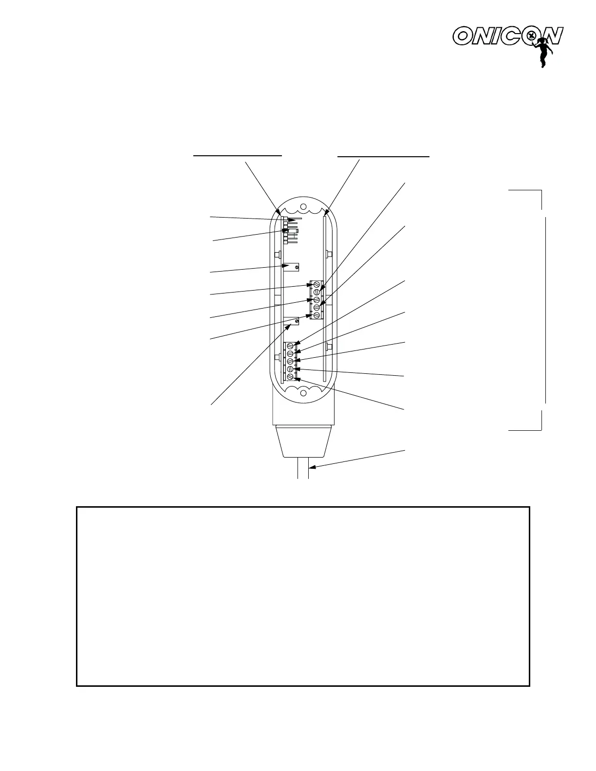
WIRING DIAGRAM
INTERNAL CONNECTIONS FOR
FLOW METERS
MODELS F-1110 / F-1210 / F-1310
SENSING BOARD
ANALOG BO
ARD
EXTERNAL CABLE CONNECTIONS
NOTES:
4-20 mA OUTPUT
(BLUE WIRE)
0-10 V OUTPUT
(BROWN WIRE)
FREQUENCY OUTPUT
(GREEN WIRE)
COMMON GROUND
(BLACK WIRE)
24V AC/DC SUPPLY
(RED WIRE)
TOP TURBINE:
F-1210 ONLY
(WHITE WIRE)
BOTTOM TURBINE:
F-1210 ONLY
(ORANGE WIRE)
EXTERNAL CABLE
NOTE: CONNECTIONS
OMITTED FOR CLARITY
TEST SIGNAL INPUT
RANGE JUMPER
(FACTORY SELECTED)
4 mA ZERO ADJUST
BLACK WIRE (BOARD TO BOARD)
GREEN WIRE (BOARD TO BOARD)
RED WIRE (BOARD TO BOARD)
10 V & 20 mA SPAN ADJUST
NON-ISOLATED ANALOG OUTPUT
For use with serial numbers
115692 and later
1500 North Belcher Road, Clearwater, Florida 33765 Tel (727) 447-6140 Fax (727) 442-5699
www.onicon.com E-mail: sales@onicon.com
0016-2 08-00
 Loading...


