1500 North Belcher Road, Clearwater, FL 33765 • Tel (727) 447-6140 • Fax (727) 442-5699 • sales@onicon.com
Turbine Flow Meter Manual 05/13 - 0721-1 / 13518 Page 44
1500 North Belcher Road, Clearwater, Florida 33765 • Tel (727) 447-6140 • Fax (727) 442-5699
www.onicon.com • sales@onicon.com
0881 / 20082
12-12
Installation Hardware Instructions
Standard Installation Kit For 1” Copper Tube
(Complies with NSF61)
For F-1100 Series Insertion Turbine Flow Meters
This kit must be installed prior to lling the system, or into a section of pipe that is isolated from
pressure and ow. Once installed, this kit allows for insertion and removal of the ow meter without a
system shutdown.
For Use With Kit INSTL3 (1”)
Directions:
1. Identify an appropriate location for the ow meter
(see next page).
2. Solder or braze the copper tee and adapters provided.
3. Install the ball valve as shown below. Use a paste type
thread sealant. DO NOT use Teon
®
tape.
4. Flush and ll the system prior to installing the meter.
NOTE: Before installing the ow meter, read the entire
installation manual.
Important Note
ONICON insertion ow meters
are precision measuring devices
that must be installed according to
the instructions contained in this
document in order to maintain their
accuracy and reliability. Failure to
follow these instructions will result
in erratic operation and reduced
accuracy.
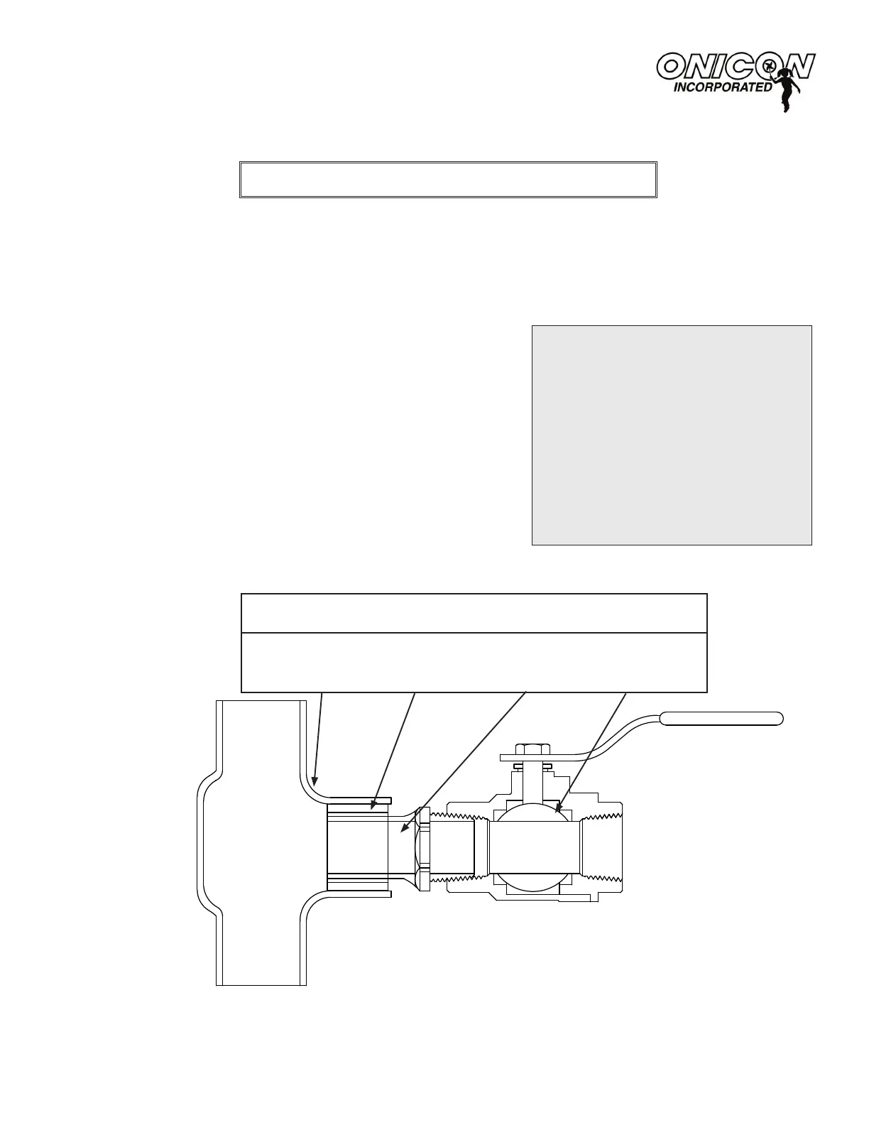
INSTALLATION KIT COMPONENTS
1” COPPER 1¼” - 1” REDUCER 1” STREET 1” FULL PORT
TEE WITH BUSHING ADAPTER BALL VALVE
1¼” OUTLET
(see Sections 3.1 and 3.2).
 Loading...


