0099-1
8-16-00
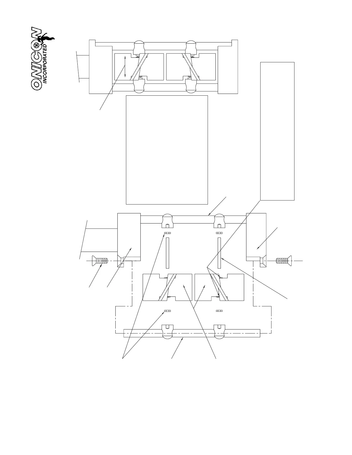
TURBINE ASSEMBLY DETAILS
for
ALL MODELS IN F-1200 SERIES
2-56 STAINLE SS, PHILLIPS HEAD SCREWS.
Clean phillips head grooves with a sharp instrument
before trying to loosen screws in a meter which has
been in service.
UPPER SUPPORT
REMOVABLE
SUPPORT POST
SAPPHIRE JEWEL
THRUST BEARINGS
TURBINE
ROTORS
LOWER
SUPPORT
Turbines must be free to slide
back and forth on the shaft with
at least .015" of movement.
TUNGSTEN CARBIDE
TURBINE SHAFT
NON-REMOVABLE
SUPPORT POST
Replace turbines in the same upper or
lower location and in the same end-for-
end relationship to the direction of flow.
(Mark one end of each turbine and the
same end of the upper support with a per-
manent felt tip marker)
After re-assembly, test the turbines for
free rotation by gently blowing on the tur-
bines PARALLEL TO THEIR SHAFTS.
The turbines must spin freely and must
have a minimum of .015" of free end play.
SAPPHIRE JEWEL RADIAL BEARINGS
If these bearings are removed from the turbines or
loosened at all, the flow meter must be returned to
the factory for recalibration or the turbines must be
1500 North Belcher Road, Clearwater, Florida 33765 Tel (727) 447-6140 Fax (727) 442-5699
www.onicon.com E-mail: sales@onicon.com
replaced.
 Loading...


