1500 North Belcher Road, Clearwater, FL 33765 • Tel (727) 447-6140 • Fax (727) 442-5699 • sales@onicon.com
System-10-LON Network Interface Installation Guide 07/13 - 0654-4 / 16751 Page 6
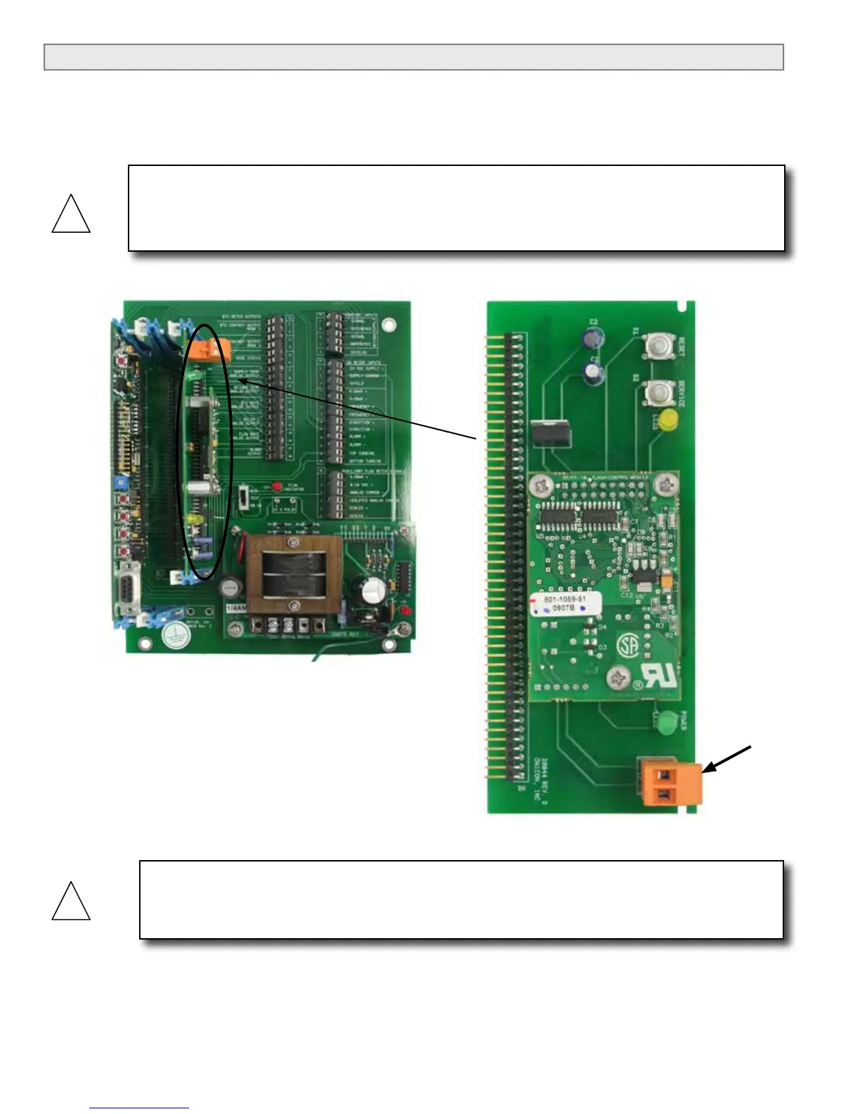
1.4 NETWORK SIGNAL CONNECTIONS
1.4.1 Lon Talk
Lon Talk, 2-wire serial output connections are connected to terminal T1 as shown. Do not
exceed 4.4 in-lb (0.5 Nm) of torque when tightening.
CAUTION
Only qualied service personnel should make connections between the System-10 BTU Meter
and the user’s external equipment. ONICON assumes no responsibility for damage caused to
the external equipment as a result of an improper installation.
CAUTION
Incoming and outgoing cable shield wires should be connected together, but must not be
connected to the System-10.
T1
 Loading...


