EasyManua.ls Logo

Onkyo A-R700

Onkyo A-R700
25 pages
To Next Page IconTo Next Page
Loading...
ONKYO.
SERVICE
MANUAL
Integrated
Stereo
Amplifier
MODEL
A-R700
UG
220V
AC,
50Hz
|
‘UOQA
240V
AC,
50Hz
|
UW
|
120V/220V
AC,
50Hz/60Hz
|
SAFETY-RELATED
COMPONENT
WARNING!!
COMPONENTS
IDENTIFIED
BY
MARK
A
ON
THE
SCHEMATIC
DIAGRAM
AND
IN
THE
PARTS
LIST
ARE
CRITICAL
FOR
RISK
OF
FIRE
AND
ELECTRIC
SHOCK.
REPLACE
THESE
COMPONENTS
WITH
ONKYO
PARTS
WHOSE
PARTS
NUMBERS
APPEAR
AS
SHOWN
IN
THIS
MANUAL.
MAKE
LEAKAGE-CURRENT
OR
RESISTANCE
MEA-
SUREMENTS
TO
DETERMINE
THAT
EXPOSED
PARTS
ARE
ACCEPTABLY
INSULATED
FROM
THE
SUPPLY
CIRCUIT
BEFORE
RETURNING
THE
APPLIANCE
TO
THE
CUSTOMER.
TABLE
OF
CONTENTS
REF.
NO.
3376
Item
Specifications
Precautions
Block
diagram
Chassis
exploded
view
'
Adjustment
procedures
Circuit
description
IC
block
diagram
Printed
circuit
board
parts
list
Packing
part
list
System
connections
Front
panel
facilities
Printed
circuit
board
view
Schematic
diagram
.
‘ONKYO
|
AUDIO
COMPONENTS
|
Question and Answer IconNeed help?

Do you have a question about the Onkyo A-R700 and is the answer not in the manual?

Onkyo A-R700 Specifications

General IconGeneral
Power Output80 watts per channel into 8Ω (stereo)
Frequency Response20Hz to 20kHz
Total Harmonic Distortion0.08%
Signal-to-Noise Ratio100dB (line)
Input Sensitivity0.2mV (MC), 2.5mV (MM), 150mV (line)
Speaker load impedance4-16 ohms
Dimensions435 x 131 x 369mm
Weight9.2kg
Damping factor60

Summary

Safety-Related Component Warning

Specifications

Precautions

Replacing the Fuses

Guidelines for replacing fuses with the same type and rating to prevent fire risk.

Insulation Resistance Measurement (USA Model)

Procedure for measuring insulation resistance on the USA model, requiring over 10 MΩ at 500V.

Voltage Selector (Rear Panel)

Instructions for using the voltage selector to match local power supplies for worldwide models.

Block Diagram

Chassis Exploded View

Chassis Exploded View Parts List

Adjustment Procedures

Preparations for Adjustment

Steps to prepare the unit and workbench before starting adjustments and checking protection circuitry.

Idling Current Adjustment

Procedure to adjust the idling current, requiring warm-up and setting voltage at a specific test point.

Protection Circuitry Operation Check

Tests for protection relay operation, DC detection, and servo circuitry using signal inputs and loads.

Circuit Description

Input Selector Circuit Description

Explanation of how the input selector operates using a rotary encoder and microprocessor signals.

Operation on Power Switch ON

Details the initialization process and initial operations when the unit's power is switched on.

IC Block Diagram

Printed Circuit Board Parts List

Tone Control Circuit PC Board Parts List

Stand-by LED PC Board Parts List

Stand-by Switch PC Board Parts List

Speaker Switch PC Board Parts List

Remote Control Sensor PC Board Parts List

Power Switch Circuit PC Board Parts List

Input Selector Key PC Board Parts List

Micro Processor Circuit PC Board Parts List

Power Amplifier Circuit PC Board Parts List

Speaker Terminal PC Board Parts List

Power Supply PC Board Parts List

Packing Parts List

System Connections

Front Panel Facilities

Power Button

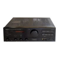
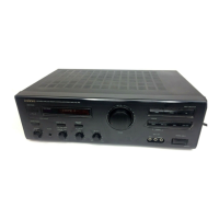
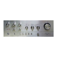
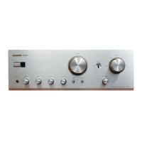
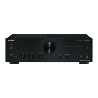
Description of the power button and its indicator, used to turn the unit on/off.

Remote Control Sensor

Description of the sensor that receives signals from the remote control transmitter.

MutingStand-by Indicator

Indicates unit status: STAND-BY mode, power on/off, or muted operation.

Muting Switch

Reduces volume level to one-tenth when set to the -20dB position.

Mode Selector Switch

Selects between STEREO and MONO listening modes.

Volume Control Knob

Controls the audio volume, with variable tone boosting system.

Input Selector Buttons and Indicators

Buttons to select program source, with indicators showing the selected source.

Speaker Selector Switch

Allows selection of speaker systems A, B, or both, or OFF for headphones only.

Headphone Jack

Stereo headphone jack for connecting headphones with a standard binaural plug.

Bass Control Knob

Adjusts bass levels, with a defeat position to bypass tone control circuitry.

Treble Control Knob

Adjusts treble levels, with a defeat position and high-cut filter function.

Variable Tone Boosting System

Explains how tone control effects are reduced as volume increases.

Balance Control Knob

Source Direct Switch

Recording Source Selector Switch

Cartridge Selector Switch

Printed Circuit Board View (Bottom Side)

Schematic Diagram

Related product manuals