ANTENNA
FM
75
AM
REMOTE
CONTROL
CENTER
SPEAKER
SURROUND
SPEAKERS
R
L
IN
IN IN
L
L
R
FRONT
CENTER
SURR
SUB
WOOFER
RL
1
2
COAXIAL
CAUTION:
SPEAKER IMPEDANCE
6 OHMS MIN. PER EACH
SPEAKER TERMINAL
OUT
IN
A
B
R
L
FRONT SPEAKERS
R
L
R
L
IN
OUT
VIDEO
DIGITAL INPUT
MONITOR
OUT
S VIDEO
DVD
VIDEO1
VIDEO 2
PHONO
CD
SUB
WOOFER
PRE OUT
TAPE
DVD
VIDEO 2
VIDEO 1
R
L
OPTICAL
IN
IN
MULTI
CHANNEL INPUT
MONI-
TOR
OUT
GND
120V
VOLTAGE SELECTOR
220-230V
SWITCHED
TOTAL 100W MAX.
AC OUTLETS
AV RECEIVER
MODEL NO.
TX-DS494
RATING:
50/60 Hz 260W
AC 120/220-230V
10kHz
9kHz
AM FREQUENCY
STEP
10kHz
9kHz
AM FREQUENCY
STEP
ANTENNA
FM
75
AM
REMOTE
CONTROL
CENTER
SPEAKER
SURROUND
SPEAKERS
R
L
IN
IN IN
L
L
R
R
FRONT
CENTER
SURR
SUB
WOOFER
RL
1
2
COAXIAL
CAUTION:
SPEAKER IMPEDANCE
6 OHMS MIN. PER EACH
SPEAKER TERMINAL
OUT
IN
A
B
R
L
FRONT SPEAKERS
R
L
R
L
IN
OUT
VIDEO
DIGITAL INPUT
MONITOR
OUT
S VIDEO
DVD
VIDEO1
VIDEO 2
PHONO
CD
SUB
WOOFER
PRE OUT
TAPE
DVD
VIDEO 2
VIDEO 1
R
L
OPTICAL
IN
IN
MULTI
CHANNEL INPUT
MONI-
TOR
OUT
GND
120V
VOLTAGE SELECTOR
220-230V
SWITCHED
TOTAL 100W MAX.
AC OUTLETS
AV RECEIVER
MODEL NO.
TX-DS494
RATING:
50/60 Hz 260W
AC 120/220-230V
10kHz
9kHz
AM FREQUENCY
STEP
120V
VOLTAGE SELECTOR
220-230V
1. Replacing the fuses
3. Safety-check out
(Only U.S.A. model)
After correcting the original service problem perform the
following safety check before releasing the set to the customer
Connect the insulating-resistance tester between the plug of
power supply cord and terminal GND on the back panel.
Specifications: More than 10Mohm at 500V
This symbol located near the fuse indicates that the
fuse used is show operating type, For continued protection against
fire hazard, replace with same type fuse , For fuse rating, refer to
the marking adjest to the symbol.
Ce symbole indique que le fusible utilise est e lent.
Pour une protection permanente, n'utiliser que des fusibles de meme
type. Ce demier est indique la qu le present symbol est apposre.
1. Press and the hold down the VIDEO 1 button , then press the
SPEAKER A button when the nuit is Power ON.
2. After " CLEAR " is displayed, the preset memory and each mode
stored in the memory, are initialized and will return to the
factory settings.
2. To initialize the unit
This unit does not require memory preservation batteries. A built-in
memory power back-up system preserves the contents of the
memory during power failures and even when the unit is un-plugged.
The unit must be plugged in order to charge the back-up
system.
The memory preservation period after the unit has been unplugged
varies depending on climate and placement of the unit. On the
average, memory contents are protected over a period of a few
weeks after the last time the unit has been unplugged. This pe-riod
is shorter when the unit is exposed to a highly humid cli-mate.
F911
252166 6.3A-UL/T-237, Fuse <DD,WT,WR,490>
F922
252077 or 4A-SE-EAK or
252243 4A-SE-TL250V, Fuse <PP,WT,WR,GT,PA>
F923
252075 2.5A-SE-EAK, Fuse <PP>
[NOTE]
<DD> : 120V model only
<DT> : Asian model only for 120V
<GT> : Asian model only for 230V
<PP> : European model only
<WT> : World wide model only
<WR> : Chinese model only
<490> : HT-R490 only
REF. NO. PART NO. DESCRIPTION
This device employs a microprocessor to perform various
functions and operations. If interference generated by an external
power supply, radio wave, or other electrical souce results in accident
which causes the specified operations and functions to operate
abnormally.
To perform a result, please follow the procedure below.
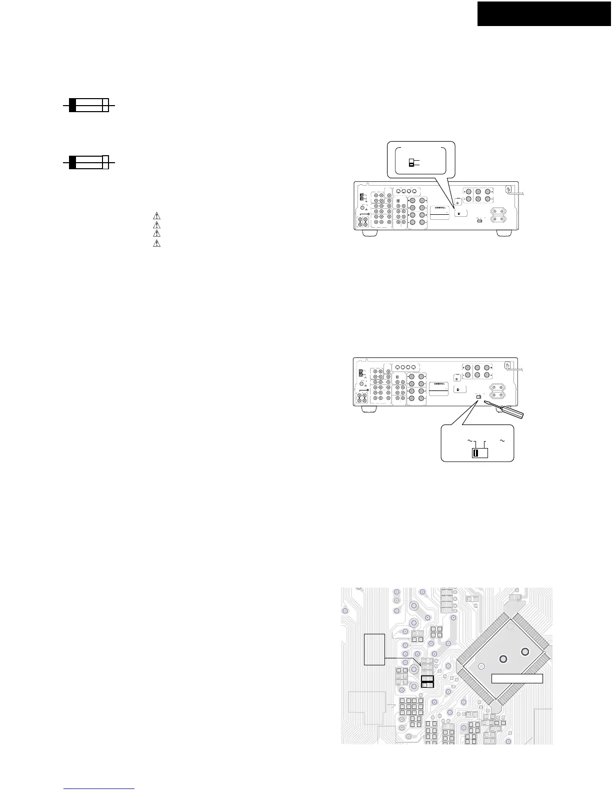
With the exception of the worldwide models, a tuning step selector
switch is not provided. When you change the band step, change
the parts as shown below.
To 10kHz To 9kHz
R7020 Open 10k
R7021 10kohm 8.2kohm
4. Memory Preservation
7. Changing the AM band step
5.Setting the AM tuning step frequency
(World wide models only)
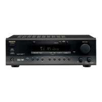
6.Setting the voltage selector
(Worldwide models only)
Worldwide models are equipped with a switch that controls
the AM band tuning step. Please set this switch to match the
AM band tuning step frequency in your area.
World models are equipped with a voltage selector
conform with local power supplies. Be sure to set this switch to
match the voltage of the power supply in your area before
plugging in the unit.
Determine the proper voltage for your area: 230V or 120V.
If the preset voltage is not correct for your area, insert a screwdriver
into the groove in the switch. Slide the switch all the way to the right
(120V) or to the left(220V-230V), whichever is appropriate.
NADIS-7043 (Display circuit PC board)
From soldering side
Microprocessor
SERVICE PROCEDURES
 Loading...