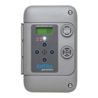
6000 Series Digital Gas Monitor/Controller
5.3 Default Conguration
Monitors are shipped pre-loaded with default settings which can
be changed in the eld to suit the desired sequence with simple
keypad input. When a monitor goes into alarm level 1, 2 or 3 it
activates its relays and transmits a message to other sensors to
activate their relays also. Alarm 3 message are transmitted by
default, but the receive option 38 defaults to 0 so the audible
alarms and strobe operate locally and not everywhere. The
ventilation system can be connected to any of the relays (usually
level 1 relay). The default conguration for one ventilation zone.
Default alarm settings are for general guidance and testing and
should be set to suit local regulations.
5.4 Creating Zones or Groups
To control multiple zones on the same network, set the transmit
message on each sensor to different messages for different
zones. The default transmit messages are 1, 2, 3 for alarm levels
1, 2, 3 for zone 1.
For zone 2 monitors set transmit messages to 4, 5, 6
For zone 3 monitors set messages to 7, 8, 9, and so on
5.5 Addresses
Set each monitor and controller to a different address (setting
39). 1, 2, 3, 4 etc. It is important to have no duplicates on the
same network cable.
5.6 Output Relays
Relay number 1 and 2 will activate if the gas on that monitor
goes into alarm level 1, or 2. It will also activate when it sees
it’s receive code (setting 36, 37) on the network, sent by other
sensors. If more than 2 relays are needed, add a model 6100
Relay Expansion Unit which has 4 additional relays. It can be
installed anywhere on the CAN network.