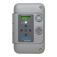
6000 Series Digital Gas Monitor/Controller
3.3 Installation Check List
Important. All wiring must conform to local building codes,
regulations and laws. If the equipment is used in a manner not
specied by the manufacturer, the protection provided by the
equipment may be impaired.
1. Use ½ inch EMT conduit for all wiring.
2. A switch or circuit breaker must be included in the installation. It
must be suitably located and easily reached in a secure location
and identied as the disconnect for the “Gas Monotoring System”.
3. Install enclosed 120/24 vac transformer. For the size of transformer
allow 5 va for each sensor or controller. Use 18 to 20 AWG two
conductor wire. Do not tie the secondary to ground. Connect
multiple monitors to one transformer. Ensure that the polarity of the
AC connections is the same at each monitor or controller, otherwise
communication will not function.
4. Connect relay contacts (usually relay 1) to ventilation system.
Use a magnetic starter so that the sensor contacts energize the
starter coil and not the fan motor directly.
5. For multiple monitors, inter-connected using the CAN network.
Connect a shielded twisted pair cable 22 to 24 AWG from
screw “L” and “H” (screw 11 and 12) on one sensor, to the next
monitor and continue chain to the last sensor. Maintain the same
polarity on each unit. Do not use star, T, or H junctions, only a
continuous chain. Make all chain connections at the sensors.
Connect shield to “S” on the rst sensor or controller only and
join shields together at each sensor/controller after the rst.
6. Move the end-of-line jumper (the one above terminal 11, 12) to
the on position (UP) on the rst monitor (or controller) on the chain
and the last monitor/controller on the chain. A controller with no
sensor module can be located anywhere on the chain. Ensure its
EOL jumper is off (down) if it is in the middle. Monitor/controller
addresses can be in any location on the chain.
7. Power on the units. They will display the gas type and reading.
To verify if monitors are communicating correctly, change setting