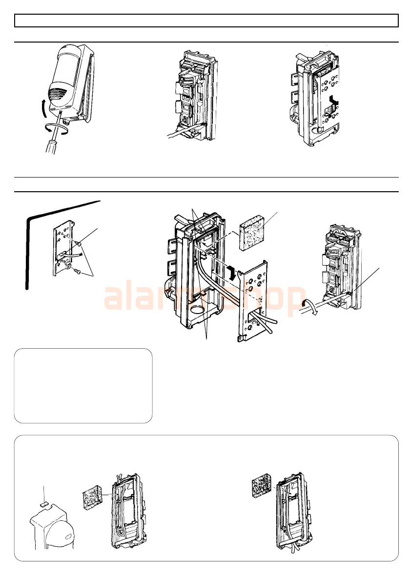
3.INSTALLATION
Loosen the lock screw and
remove the cover.
3-1.Before the Installation
Loosen the plate lock screw
[about 10mm (0.4")].
3-2.Wall Mount
(a)Upper Knockout Wiring Hole (b)Lower Knockout Wiring Hole
Remove the lower
knockout of the
unite cover, lead
the wire through
the knockout hole.
Remove the upper
wire knockout.
Pull the wire through wiring hole and
install the plate on the wall by using
provided mounting screws (two places).
Fasten the plate lock screw and
connect the wires to the terminal.
Lead the wire to the groove
on the unit base, through the
wiring hole at the terminals.
Apply an adhesive sponge pad
over the wiring hole. Hook the
unit base onto the plate.
Adjust the DIP switch, detection
area and sensitivity. Secure the
cover with the lock screw.
Remove the plate by sliding it down
and away from the unit base.
Lead the wire through
the upper side of the
unit base, lead the wire
to the wiring slit then
through the wiring hole.
-4-
IMPORTANT
• Install the unit perpendicular.
• Installation height must be between
0.8m and 1.2m (2.7 ft and 4 ft).
• Secure a space 110mm (4.4") or
more to the upper part of plate for
opening and closing of the cover.
Surface wiring
Wiring Groove
Wiring Hole
( Terminals)
Wiring Sponge Pad
Plate Lock
Screw
Wiring Hole
Mounting Screw
T4 x 20
 Loading...