CRYO-LINE Manual for installation and use
OPTIKON 2000
Code 131002 EN 2014-02-06 Rev.F
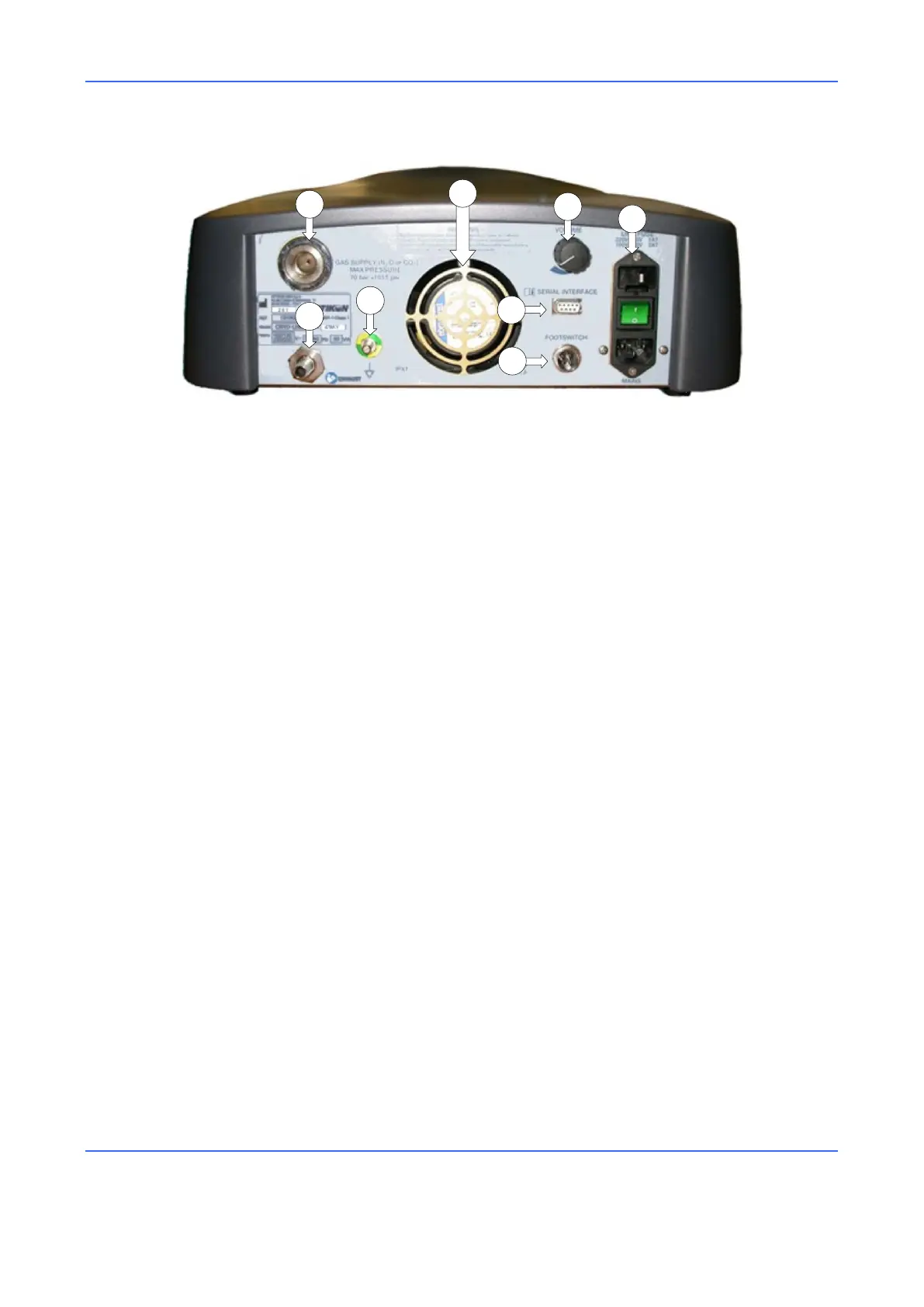
Figure 2. Rear View
1) GAS CONNECTOR
Connector for high-pressure gas input.
2) COOLING FAN
Removes the hot air from the unit.
3) VOLUME CONTROL KNOB
This knob allows the operator to adjust the volume of the sound signals generated
by the CRYO-LINE unit.
4) POWER SUPPLY (ON/OFF SWITCH GROUP)
The main switch turns the unit on/off. The fuses, mains voltage selector and
power cord socket are located near this switch.
5) FOOTSWITCH CONNECTOR
This is the port for the connector of the footswitch that, when pressed, activates
the functions of the CRYO-LINE unit.
6) SERIAL CONNECTOR
This connector allows to connect the CRYO-LINE unit to a PC through a serial
connection. This connector is used for technical servicing of the instrument.
7) EQUIPOTENTIALITY CONNECTION
Connector for the verification of the zero potential of the instrument.
8) GAS EXHAUST CONNECTOR
A hose for the evacuation of the gas outside the operating room must be
connected to this outlet.