CRYO-LINE Manual for installation and use
OPTIKON 2000
Code 131002 EN 2014-02-06 Rev.F
7.2 CONFIGURATION OF THE UNIT
This section contains information on the configuration of the unit. All the operational
controls and adjustments are identified and described below.
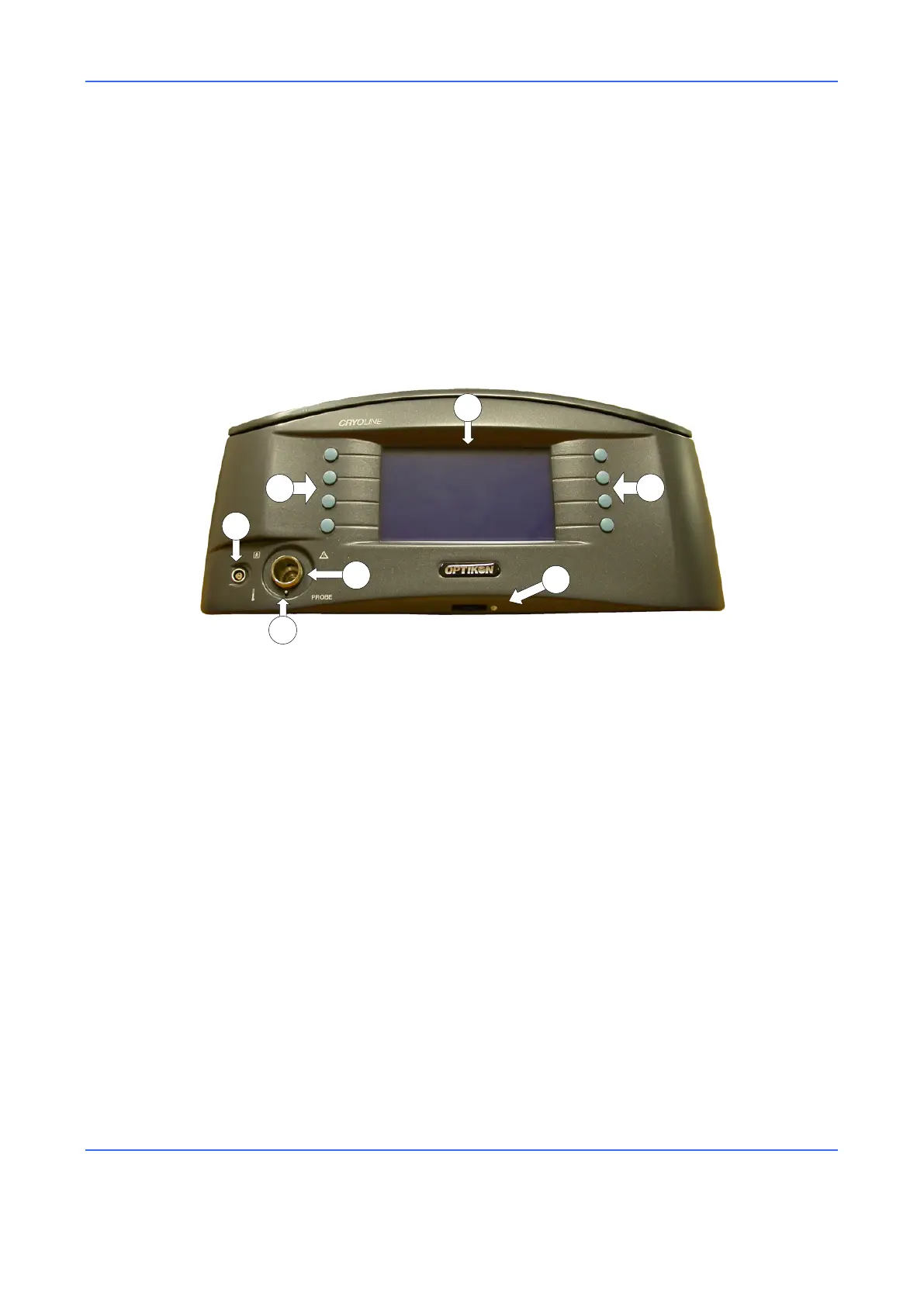
The connectors and other elements of the instrument are described in Figure 1. The
connectors of the rear panel and other elements are described in Figure 2.
Figure 1. Front View
1) BACKLIT LCD DISPLAY
This display allows the operator to do the following:
See which functions are activated
Read all the effective and preset values
Read the warnings and error messages
2) BUTTONS
Silicone keys with which it is possible to select the different functions of the unit.
3) CONTRAST CONTROL
Contrast adjustment roller for the Display.
4) PROBE CONNECTOR
The pneumatic line of the cryosurgical probe connects to this outlet.
5) SAFETY SWITCH
This pin interlock blocks the passage of gas if the probe is not inserted.
6) THERMOCOUPLE CONNECTOR
The connector of the cryosurgical probe thermocouple connects to this socket.
 Loading...


