0
50V
70V
100V
4
Ω
8
Ω
16
Ω
SPEAKERS
LINE
OUTPUT
POWER
STAGE
PRIORITY
CONTROL
INPUT
MASTER
PRIORITY
MASTER
PROGRAM
PRI-PRO
LINK
PROGRAM
PRIORITY
PROTECTION
PRIORITY OUTPUT
PRIORITY INPUT
PROGRAM OUTPUT
PROGRAM INPUT
SURETY
PAGING
FAIL
SURVEILLANCE
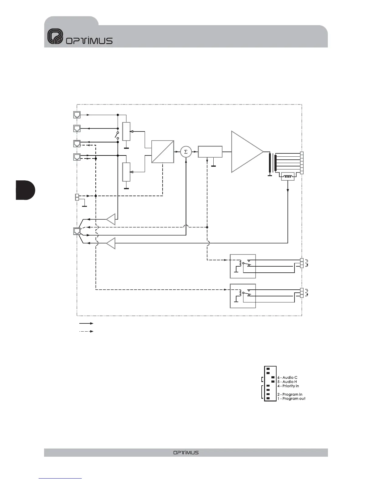
Priority & Control Signal
Audio
5. BLOCK DIAGRAM
6. FACTORY SETUP CONFIGURATION
Priority contact from the RJ45 Priority Output connector: ON
Priority contact from the RJ45 Priority Input connector: ON
Priority and Program Audio link: OFF
Cable and RJ45 shield link to amplifier ground:ON
ON OFF
PRI-PRO LINKPRI-PRO LINK
SHIELD-GND
LINK
SHIELD-GND
LINK
7 - Priority ctrl. in7 - Priority ctrl. in
8 - Priority ctrl. out8 - Priority ctrl. out
3 - Priority out3 - Priority out
DIPSWITCH CONFIGURATION
OTHER CONFIGURATION
JP1 (internal jumper) = OFF
JP2 (internal jumper) = ON
Surveillance Shield - Ground Link
Eng
AMPLIFIERS UP-367, UP-247, UP-127 and UP-67
ENGLISH
20
UP-367, UP-247, UP-127 and UP-67Version 1.0