SURVEILLANCE CONNECTOR
VENTILATION OUTPUT
Do not obstruct this output under any
circumstances.
UP-367 and UP-247
UP-127
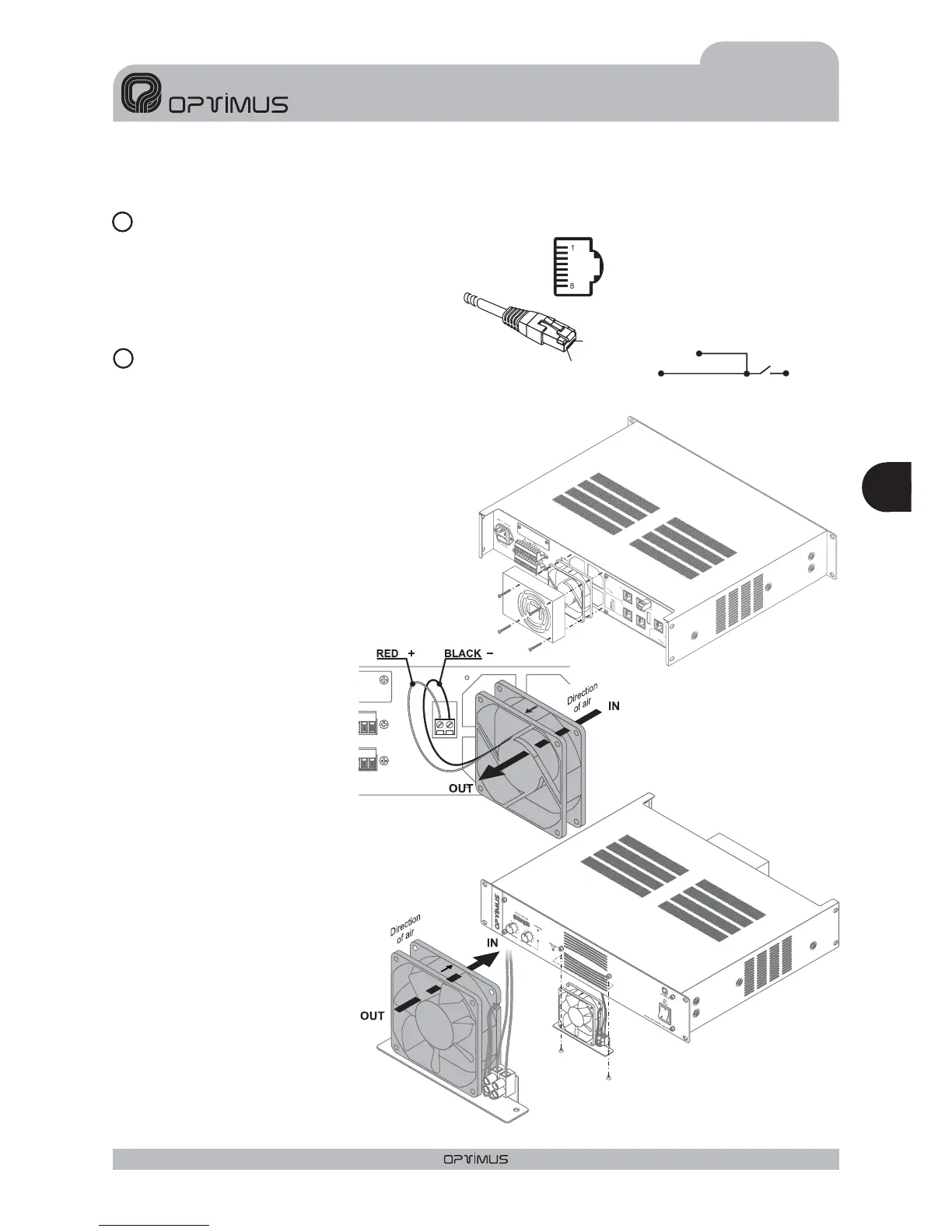
It is used to link the amplifier with the speaker's
line surveillance card, where required.
For the connection use shielded RJ45
connectors (see figure 9).
Equipped with one front and one
rear fan. The front fan is activated
when the interior temperature
reaches 65ºC. The rear fan is
activated when the interior
temperature of the amplifier
reaches 100ºC. This should only
occur in extreme conditions, since,
with respect to its size, the unit has
been designed not to require
activationof the rear fan.
If the internal temperature of the
unit were to exceed 110ºC, the
protection device of the unit itself
would be activated.
Equipped with a front fan. This is
activated when the interior
temperature reaches 100 ºC. This
should only occur in extreme
conditions, since, with respect to its
size, the unit has been designed not
to require the fan.
If the internal temperature of the
unit were to exceed 110 ºC, the
protection device of the unit itself
would be activated.
To replace the rear and/or front fan
follow the indications in figures 10
and 11.
4. VENTILATION SYSTEM
14
GND
1
8
1
8
JP2
(internal jumper)
15
Figure 10
Figure 9
Figure 11
Eng
19
UP-367, UP-247, UP-127 and UP-67 Version 1.0
ENGLISH
AMPLIFIERS UP-367, UP-247, UP-127 and UP-67
Pin number 1: OSCILLATION INPUT
: OSCILLATION OUTPUT 1
: PROTECTION OUTPUT
: OSCILLATION OUTPUT 2
Pin number 6: PRIORITY OUTPUT
Pin number 7: +24VDC OUTPUT
8:
Shield
Pin number 3
Pin number 4
Pin number 5
Pin number
O
N
O
F
F
S
U
R
V
E
IL
L
A
N
C
E
R
J
45
C
O
N
N
E
C
TIO
N
7
8
6
5
2
3
1
1
.
O
S
C
IN
2
.
N
C
3
.
O
S
C
O
U
T
1
4
.
P
R
O
T
E
C
T
5
.
O
S
C
O
U
T
2
6
.
P
R
I
O
U
T
7
.
+
2
4
V
D
C
O
U
T
P
U
T
8
.
M
E
T
A
L
S
H
IE
L
D
G
N
D
D
IP
S
W
IT
C
H
C
O
N
F
IG
U
RA
TIO
N
O
N
O
F
F
8.
P
riority
c
trl.
o
ut
7.
P
riority
c
trl.
i
n
6.
A
udio
C
5.
A
udio
H
4.
P
riority
I
n
3.
P
riority
o
ut
2.
P
rogram
i
n
1.
P
rogram
o
ut
PRI-PRO
LINK
SHIELD-GND
LINK
1
.
A
U
D
IO
S
IG
N
A
L
H
2
.
A
U
D
IO
S
IG
N
A
L
C
(
W
H
E
N
B
A
L
A
N
C
E
D
)
3
.
+
2
4
V
D
C
O
U
T
P
U
T
6
.
P
R
I
O
R
I
T
Y
8
.
M
E
T
A
L
S
H
IE
L
D
G
N
D
PR
IO
R
IT
Y
&
P
R
O
G
R
A
M
R
J
4
5
C
O
N
N
E
C
TIO
N
SURVEILLANCE
PRIORITY
INPUT
PRIORITY
OUTPUT
PROGRAM
INPUT
PROGRAM
OUTPUT
PRIORITY
CTRL.
I
NPUT
GND
OPTIMUS
S
.A.
UP-247
POWER
A
MPLIFIER
240W
R
MS
(
312W
I
HF)
Engineering& Q.A.
From
EU(Spain)
Madein China
UP-247