Front and Back View
The CloudGate Base Unit is assembled in the top half of the device. The bottom half is
available to insert expansion cards.
The front and back side of the CloudGate housing are closed by means of metal
panels that are secured with Torx T6 screws.
The top panels are designed by Option and cannot be changed, since they provide
the interfaces of the base unit. The bottom panels can be customized to match the
external interfaces of the expansion card.
Front View
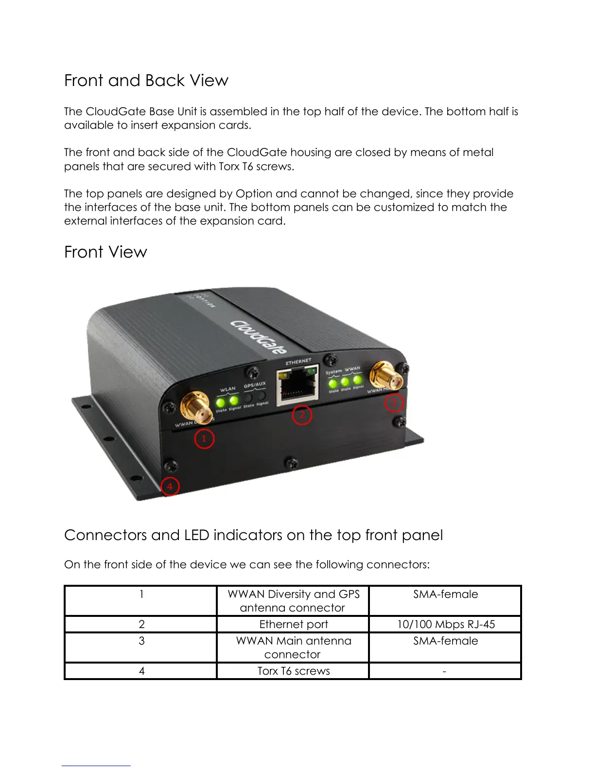
Connectors and LED indicators on the top front panel
On the front side of the device we can see the following connectors:
1 WWAN Diversity and GPS
antenna connector
SMA-female
2 Ethernet port 10/100 Mbps RJ-45
3 WWAN Main antenna
connector
SMA-female
4 Torx T6 screws -
7