3-22
OPERATION ORBAN Model 6200
vide less compression and a frequency balance that is maximally faithful to
the source material.
The Two-Band Structure’s Full Setup Controls
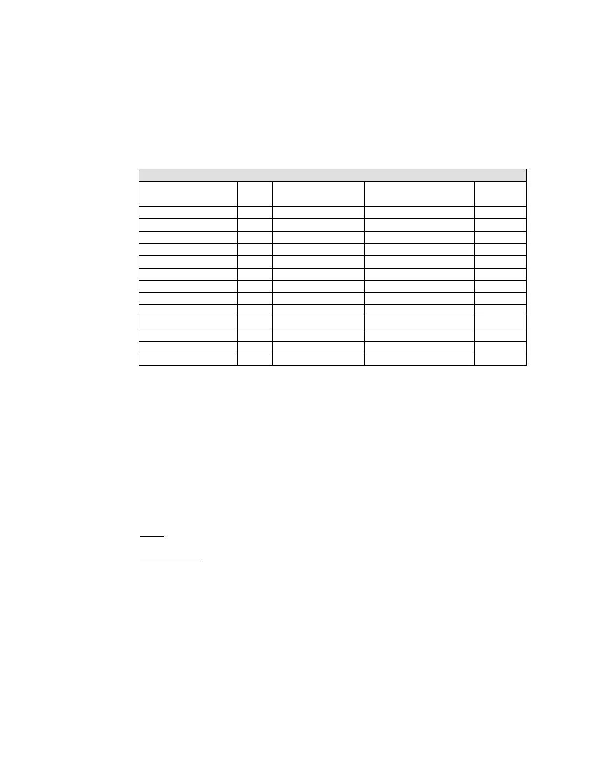
The table shows a summary of the Two-Band controls:
2B FULL CONTROL
Parameter Labels Units Default Range (CCW to CW) Step
AGC --- on off, on ---
AGC DRIVE dB (per L/M tables)
−10 … 0 … 25
1
AGC REL dB/S (per L/M tables) 0.5, 1.0, 1.5, 2 … 20 1
AGC B CPL % (per L/M tabels) 0 … 100 5
GATE THR dB (per L/M tables)
off, −44 … −15
1
2B DRIVE dB (per L/M tables) 0 … 25 1
2B REL dB/S (per L/M tables) 0.5, 1.0, 1.5, 2 … 20 1
LC THRESH dB (per L/M tables) -3.0 … +3.0, off 0.5
BASS CPL % (per L/M tables) 0 … 100 5%
BASS CLIP dB (per L/M tables)
−6.00 … 0.00
0.25
FINAL LIMT dB (per L/M tables) 0.00 … +6.00 0.25
LESS-MORE --- (per preset)
(read-only)
---
PARENT PRESET --- (per preset)
(read-only)
---
Table 3-4: Two-Band Controls
These controls are explained in detail below.
Each Two-Band Factory Preset has a
LESS-MORE
control that adjusts on-air loudness.
LESS-MORE
simultaneously adjusts all of the processing controls to optimize the trade-
offs between unwanted side effects as processing levels are decreased or increased.
If you wish, you may adjust the
FULL CONTROL
parameters to your own taste. Always
start with
LESS-MORE
to get as close to your desired sound as possible. Then edit the
FULL CONTROL
parameters using the Full Control screen, and save those edits to a User
Preset.
AGC
on/off control activates or defeats the slow AGC prior to the two-band compressor.
AGC DRIVE
control adjusts signal level going into the slow AGC, and therefore deter-
mines the amount of gain reduction in the AGC. This also adjusts the “idle gain” — the
amount of gain reduction in the AGC section when the structure is gated. (It gates when-
ever the input level to the structure is below the threshold of gating.)
The total amount of gain reduction in the Two-Band structure is the sum of the gain re-
duction in the AGC and the gain reduction in the two-band compressor. The total gain
reduction determines how much the loudness of quiet passages will be increased (and,
therefore, how consistent overall loudness will be). It is determined by the setting of the
AGC DRIVE
control, by the level at which the console VU meter or PPM is peaked, and
by the setting of the
2B DRIVE
control, discussed below.


 To Next Page