OPTIMOD INSTALLATION
2-7
If you want to connect the 6200 directly to a computer, use a “null modem”
cable. If you want to connect it to a modem, use a conventional computer-to-
modem cable.
In a high-RF environment, these wires should be short and should be run
through foil-shielded cable, with the shield connected to CHASSIS
GROUND at both ends.
(Most competently designed serial cables are already well shielded to pre-
vent the cable from radiating EMI to the environment.)
For complete 6200 PC installation steps, refer to the separate 6200 PC
document.
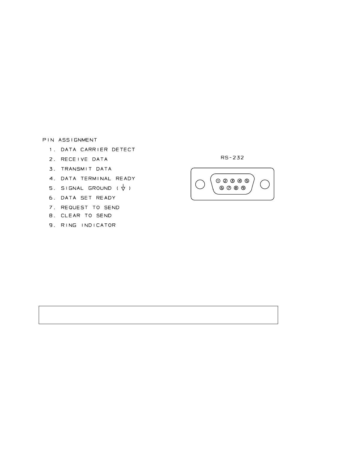
Figure 2-4: Wiring the RS-232 Computer Interface Connector
8. Connect inputs and outputs.
See the hookup and grounding information on the following pages.
Audio Input and Audio Output Connections Page 2-8
AES/EBU Digital Input and Output Page 2-10
Grounding Page 2-10
6200 Rear Panel
The Voltage Selector can be set to 115V (for 90-130V operation) or 230V (for 180-
260V operation).
Fuse values can be changed to support 115V or 230V operation. The fuse must be 3AG
Slow-Blow, ½-amp for 115V, or ¼-amp (250mA) “T” type for 230V.
The Power Cord is detachable and is terminated in a “U-ground” plug (USA standard),
or CEE7/7 plug (Continental Europe), as appropriate to your 6200’s Model Number.
The GND LIFT (Ground Lift) Switch can be set to connect the 6200’s circuit ground
to its chassis ground (in the “CHASSIS GROUND” position). In the
LIFT
position, it