2-6
INSTALLATION ORBAN Model 6200
6. Connect remote control. (optional, 6200 OPTIMOD-DAB only)
The 6200 OPTIMOD-DAB has extensive remote control provisions.
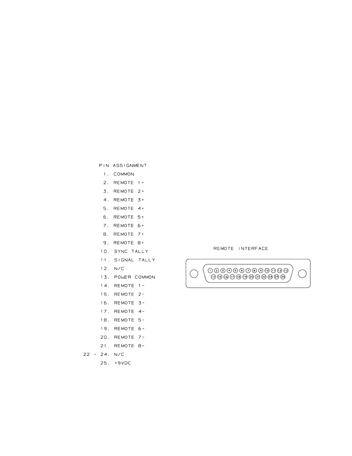
Optically isolated remote control connections are terminated in a type DB-25
female connector located on the rear panel. It is wired according to Fig. 2-3.
To select the desired function, apply a 6-24V AC or DC pulse between the
appropriate Remote terminals. The (−) terminals can be connected together and
then connected to ground at pin 1 to create a Remote Common. If you use
48V, connect a 1kΩ ±10%, 2-watt carbon composition resistor in series with
the Remote Common or the (+) terminal to provide current limiting. A current-
limited +9VDC source is available on pin 25.
In a high-RF environment, these wires should be short and should be run
through foil-shielded cable, with the shield connected to CHASSIS
GROUND at both ends.
Figure 1-3: Wiring the 25-pin Remote Control Connector
7. Connect computer interface. (optional)
The RS-232 connector is wired according to Fig. 2-4.