EasyManua.ls Logo

Oriental motor 4RK25GN-AM-115 User Manual

Oriental motor 4RK25GN-AM-115
3 pages
To Next Page IconTo Next Page
Page #1 background imageLoading...
Page #1 background image
HM-9030-2
Thank you for selecting ORIENTAL MOTOR products.
To ensure correct operations, please read these instructions
carefully before using this motor.
INSTRUCTIONS
Electromagnetic Brake Motors
Single Phase 115V, 60Hz 4RK25GN-AM-115, 5RK40GN-AM-115
Single Phase 220/240V, 50Hz 4RK25GN-CME, 5RK40GN-CME
These Electromagnetic Brake Motors are reversible motors with a built-in de-energized electromagnetic brake [Fail-Safe Brake].
These motors are designed for 115V, 60Hz or 220/240V, 50Hz power sources.
Features
1. Employing a de-energized, electromagnetic brake, the brake is
activated upon power shut off. The motor stops immediately and
holds the load firmly.
2. Sufficient holding torque is obtained regardless to the motor speed or
the power source frequency.
[Holding brake torque: 4RK25 Type 13 oz-in(9.8N-cm), 5RK40
Type 20 oz-in(14.7N-cm)]
3. The overrun at motor shaft is approximately 23 rotations.
(With no-load and motor power shut off simultaneously.)
Connecting Diagrams
Protection of the relay contacts
The motor switch (SW2) and the electromagnetic brake switch (SW3) emit sparks
when turned on and off. In order to protect the relay contacts.
CR circuit ( ) must be connected.
Co=0.10.2μF 250WV:4RK25GN-AM-115,
5RK40GN-AM-115
500WV:4RK25GN-CME,
5RK40GN-CME
Ro=5200Ω, 1/4W minimum
Switch Specifications
No. of switches
SW1
SW2
SW3
SW4
Switch specifications
Single Phase 115V
AC125V 3A
Minimum
Single Phase 220/240V
AC250V 1.5A
Minimum
Note
Move together
WHITE
Capacitor
STOP
RUN
CCW
CW
SW2*
Ro Co
SW1
GRAY
LINE
BLACK
Motor
Electro-
magnetic
Brake
STOP
RUN
OFF
ON
SW3*
Ro Co
YELLOW
YELLOW
SW4
SW2 and SW3 move together.
Timing Chart
Operations
Run/Stop
1. Motor will rotate when SW2 and SW3 are switched simultaneously to
RUN (short circuit) switching SW4 to OFF (open).
2. When SW2 and SW3 are switched simultaneously to STOP (open),
the motor stops immediately by electromagnetic brake and holds the
load.
3. To rotate the motor shaft by hand during the motor stops, switch
SW4 to ON (short circuit). The electromagnetic brake is released
and the motor shaft can be rotate easily by hand.
(Always switch SW4 to OFF (open) when running and stopping the
motor. SW4 is not necessary when such a operation is not needed.)
Direction of Rotation
To rotate the motor in a clockwise (CW) direction, switch SW1 to CW.
To rotate it in a counter-clockwise (CCW) direction, switch SW1 to
CCW.
The diagram shows the direction of rotation of the motor shaft as
viewed from the motor shaft end.
SW1
SW2
SW3
SW4
Motor
CW
ONOFF
CCW
RunStop Stop Stop
Brake Release
Run
Run
CW
CCW
CW
Stop Stop Stop
Run
Run
Stop
Load-
Holding
Run
Brake
Release
Stop
Load-
Holding
Stop
Load-
Holding
Question and Answer IconNeed help?

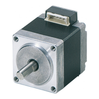
Do you have a question about the Oriental motor 4RK25GN-AM-115 and is the answer not in the manual?

Oriental motor 4RK25GN-AM-115 Specifications

General IconGeneral
Motor TypeInduction Motor
Power25 W
Voltage115 VAC
Frequency50/60 Hz
Weight1.5 kg
Insulation ClassClass B

Summary

Electromagnetic Brake Motor Features

De-energized Brake Operation

Brake activated upon power shut off, stopping motor and holding load firmly.

Holding Torque Performance

Sufficient holding torque is obtained regardless of motor speed or power source frequency.

Motor Shaft Overrun

Overrun at motor shaft is approx. 2-3 rotations when no-load.

Wiring and Operational Control

Connecting Diagrams

Diagram showing wiring for motor and electromagnetic brake switches.

Timing Chart

Chart illustrating switch states during motor run, stop, and brake release.

Motor Operation Modes

Instructions for starting, stopping, and manual rotation using switches.

Direction of Rotation Control

How to switch SW1 for CW/CCW rotation based on motor shaft view.

Protection and Specifications

Relay Contact Protection

CR circuit recommended to protect relay contacts from sparking during switching.

Switch Specifications

Details of switch types and ratings for 115V and 220/240V single phase.

Gearhead Connection and Specifications

Gearhead Models and Shaft Sizes

Lists available gearhead models and their corresponding inch/metric shaft diameters.

Precautions for Connecting Gearhead

Guidelines for safely attaching gearhead to motor, avoiding damage.

Installation and Grounding

Recommendations for firm installation, heat dissipation, vibration protection, and grounding.

Operation Precautions and Troubleshooting

Precaution on Continuous Operation

Limits on continuous operation time to prevent overheating (max 90°C).

Environmental Operating Conditions

Recommended ambient temperature (-10°C to 50°C) and humidity (85% less).

Trouble Shooting Guide

Lists common symptoms, causes, and check points for motor issues.

Related product manuals