5 Installation
−14−
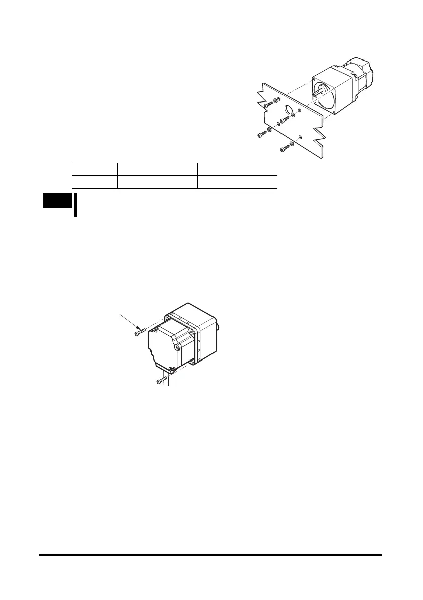
• Geared type
To install the motor, use the four installation
holes and mount the motor with four bolts (not
provided) so that there is no gap with the
mounting plate.
Effective depth of bolt: 8 mm (0.31 in.)
Unit model Nominal thread size Tightening torque
BLH015 M4 1.8 N·m (15.9 lb-in)
Note
Fit the boss on the gearhead mounting surface into a counterbore or through
pilot-receiving hole.
Changing the motor cable’s routing direction
The gearhead can be removed and the motor cable position changed to a desired 90°
direction. (BLH015 is removed)
1. Remove the hexagonal socket head screws (2 pcs.) assembling the
motor and gearhead and detach the motor from the gearhead.
Hexagonal socket head
screws
2. Using the pilot sections of the motor and gearhead as guides, install the
motor to the gearhead and tighten the hexagonal socket head screws.
At this time, the motor cable position can be changed to a desired 90° direction.
When installing the gearhead, slowly rotate it clockwise/counterclockwise to
prevent the pinion of the motor output shaft from contacting the side panel or
gear of the gearhead.
Also, confirm that no gaps remain between the motor flange surface and the end
face of the gearhead’s pilot section.
 Loading...
