6 Connection
−30−
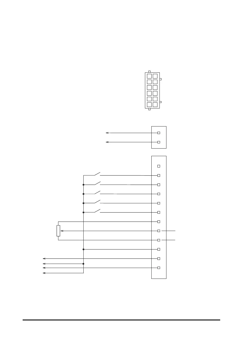
6.3 Connection of input signal and output signal
Connection with driver
Insert the connector of the I/O signals cable into the connector of the I/O signals
cable (CN2) of the driver. The colors in the figure indicate the colors of supplied
cables.
Connector pin assignments of I/O cable (CN2)
21
43
65
87
10 9
12 11
• BLH015, BLH230, BLH450
START/STOP
input
GND
+24 V
NC
OFF
ON
OFF
ON
OFF
ON
OFF
ON
OFF
ON
1
12
11
10
9
8
7
6
+
-
5
4
3
2
1
2
1
2
3
RUN/BRAKE
input
CW/CCW
input
INT.VR/EXT
input
ALARM-RESET
input
VRH
VRM
VRL
CN2
CN1
SPEED
output
GND
ALARM
output
To external control device
External
potentiometer
∗
20 kΩ 1/4 W
Power supply input
External DC power supply
∗
(For speed setting)
0 to 5 VDC
1 mA or more
Black
Red
Black
White
Gray
Light Blue
Purple
Blue
Green
Yellow
Orange
Red
Brown
24 VDC±10%
∗ Connect either the external potentiometer (accessory) or DC power supply for the external
speed setting.
 Loading...
