6 Connection
−31−
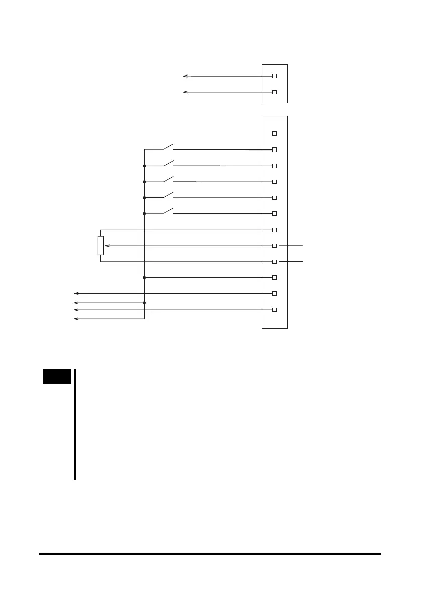
• BLH5100
START/STOP
input
+24 V
GND
NC
OFF
ON
OFF
ON
OFF
ON
OFF
ON
OFF
ON
1
12
11
10
9
8
7
6
+
-
5
4
3
2
1
2
1
2
3
RUN/BRAKE
input
CW/CCW
input
INT.VR/EXT
input
ALARM-RESET
input
VRH
VRM
VRL
CN2
CN1
SPEED
output
GND
ALARM
output
To external control device
External
potentiometer
∗
20 kΩ 1/4 W
Power supply input
External DC power supply
∗
(For speed setting)
0 to 5 VDC
1 mA or more
Red
Black
Black
White
Gray
Light Blue
Purple
Blue
Green
Yellow
Orange
Red
Brown
24 VDC±10%
∗ Connect either the external potentiometer (accessory) or DC power supply for the external
speed setting.
Note
• When extending the I/O signals cable, the length must not exceed 2 m
(6.6 ft.). To minimize noise, it should be as short as possible.
• The I/O signals cable must be located 200 mm (8 in.) or more away from
such inductive loads as electromagnetic relay, and must cross power supply
and motor cables, not parallel to them.
• If you are not using all cables from the terminals provided on the
non-connector side of the I/O signals cable, insulate the unused cables to
prevent them from contacting other devices, or depending on the
applications of these signals connect them to 5 VDC from a user-provided
external control device or to a signal ground.
 Loading...
