5 Installation
−23−
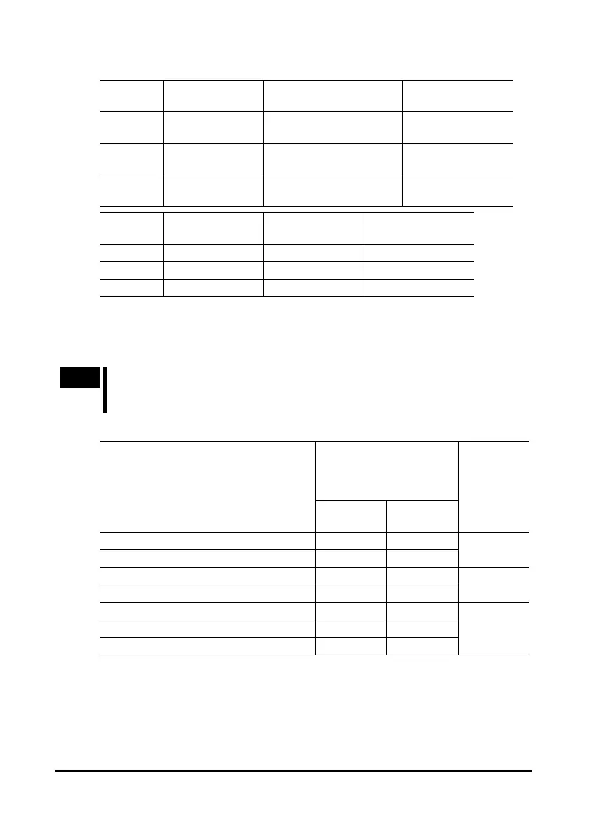
Recommended load shaft installation dimensions [Unit: mm (in.)]
Unit model
Inner diameter of
hollow shaft
Recommended tolerance
of load shaft
Nominal diameter of
retaining ring
BLH230
Ø12
+0.027
0
(Ø0.4724
+0.0011
0
)
Ø12
0
-
0.018
(Ø0.4724
0
-
0.0007
)
Ø12 (Ø0.47)
BLH450
Ø15
+0.027
0
(Ø0.5906
+0.0011
0
)
Ø15
0
-
0.018
(Ø0.5906
0
-
0.0007
)
Ø15 (Ø0.59)
BLH5100
Ø20
+0.033
0
(Ø0.7874
+0.0013
0
)
Ø20
0
-
0.021
(Ø0.7874
0
-
0.0008
)
Ø20 (Ø0.79)
Unit model Applicable screw Spacer thickness
Outer diameter of
stepped shaft (ØD)
BLH230 M4 3 (0.12) 20 (0.79)
BLH450 M5 4 (0.16) 25 (0.98)
BLH5100 M6 5 (0.20) 30 (1.18)
Permissible overhung load and permissible thrust load
Make sure the overhung load and thrust load received by the output shaft will not
exceed the allowable values shown in the table below.
Note
If the overhung load or thrust load exceeds the specified allowable value,
repeated load applications may cause the bearing or output shaft of the
gearhead to undergo a fatigue failure.
Combination type hollow shaft flat gearhead
Distance from gearhead
mounting surface and
permissible overhung load
[N (lb.)]
Unit model
∗
10 mm
(0.39 in.)
20 mm
(0.79 in.)
Permissible
thrust load
[N (lb.)]
BLH230KC-5, 10FR 450 (101) 370 (83)
BLH230KC-15, 20, 30, 50, 100, 200FR 500 (112) 400 (90)
200
(45)
BLH450KC-5, 10FR 800 (180) 660 (148)
BLH450KC-15, 20, 30, 50, 100, 200FR 1200 (270) 1000 (220)
400
(90)
BLH5100KC-5, 10FR 900 (200) 770 (173)
BLH5100KC-15, 20FR 1300 (290) 1110 (240)
BLH5100KC-30, 50, 100, 200FR 1500 (330) 1280 (280)
500
(112)
∗ For the lead wire type, “KC” of the unit model is replaced by “K”.
 Loading...
