7 Operation
−46−
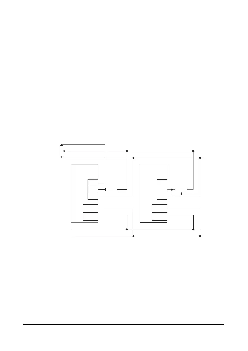
Use an external potentiometer
Use common lines for the power supply and speed control and set the speed using
VRx, as shown below.
• Obtain the resistance for the external speed potentiometer as follows:
Resistance when N drivers are connected: VRx = 20/N (kΩ), N/4 (W)
Example: If two drivers are connected, the current capacity should be 10 kΩ,
1/2 W.
• All I/O signals other than the one used for speed setting should be connected to
each driver.
• If multiple motors are used with speed differences among them, make the
following adjustments:
First motor: Connect a resistor of 1.5 kΩ, 1/4 W to the driver’s M terminal.
Second and subsequent motors: Connect a variable resistor (VRn) of 5 kΩ, 1/4 W
to the applicable driver’s M terminal.
• Keep the number of drivers to five or less in parallel operation using an external
potentiometer.
3
2VRx
1
Control line
1.5 kΩ, 1/4 W
VRn
5 kΩ, 1/4 W
H
M
L
Driver
H
M
L
Driver
Power supply
line
CN2
CN1
+24 V
GND
CN2
CN1
+24 V
GND
 Loading...
