Do you have a question about the Oriental motor FSP200-1 and is the answer not in the manual?
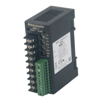
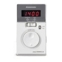
Details the display, function, and lighting conditions of controller parts and terminal blocks.
Illustrates wiring diagrams for single-phase power supplies.
Illustrates wiring diagrams for three-phase power supplies.
Specifies applicable lead wires, crimp terminals, and connection methods for motor and controller.
Details terminal connections for input/output signals, including specifications for crimp terminals.
Visualizes the timing of CW, CCW, SD, MO, and electromagnetic brake signals for operation.
Describes input signal circuits and provides connection examples for relays and electronic control.
Describes output signal circuits and provides connection examples for external devices.
Explains speed control using the internal speed potentiometer via the MO input.
Details using an external speed potentiometer for speed control via the MO input.
Explains speed control using an external DC voltage source via the MO input.
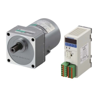
Lists combinations of motor models, gearhead models, and speed controller models.
Lists combinations for round shaft motors with specific gearheads and speed controllers.
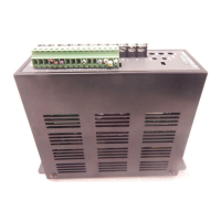
This document describes the Oriental Motor FSP200-1, FSP200-2, and FSP200-3 Speed Controllers, along with their associated motors and connection diagrams. These devices are designed for precise speed control of motors, offering various input and output options for integration into different systems.
The FSP200 series speed controllers are designed to regulate motor speed, direction, and braking. They feature both internal and external speed setting capabilities, allowing for flexible control based on application requirements. The controllers include protective functions to ensure safe operation and provide alarm outputs in case of abnormalities.
Internal Potentiometer Functions:
LED Display Functions:
Switch: A physical switch allows selection of cable length:
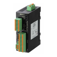
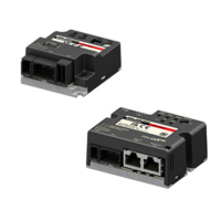
The controllers offer a comprehensive set of terminals for various input and output signals, facilitating integration with external control devices.
Input Terminals:
Output Terminals:
Motor Connection Terminals:
Power Connection Terminals:
Regeneration Unit Terminals:
Speed Setting Methods:
Timing Chart and Control Logic: The CW, CCW, MO, and SD input signals are used for comprehensive motor control:
Input Signal Circuit: Common to CW, CCW, SD, FREE*, RST inputs. The circuit includes a 2.4 kΩ resistor. The FREE input is specifically for speed control systems with electromagnetic brakes.
Output Signal Circuit: Common to S-MON, ALM outputs. These are open-collector outputs requiring an external power supply (Vcc, max 26.4 VDC) and a limit resistor (R) to keep output current below 10 mA.
Electronic Input Control: External control devices can interface with the speed controller via photocouplers for input signals.
Applicable Lead Wires:
Crimp Terminals:
Wiring Distance:
Power Supply Input:
Speed Monitor Output:
Alarm Output: The ALM output provides a signal when protective functions are activated due to:
Thermal Signal Input (TP): Allows connection of a regeneration unit's internal thermal protector, providing an additional layer of protection against overheating.
Note: Ensure the motor case temperature does not exceed 90°C (194°F) during operation.
| Brand | Oriental motor |
|---|---|
| Model | FSP200-1 |
| Category | Controller |
| Language | English |