EasyManua.ls Logo

Oriental motor MSC-1 - User Manual

Oriental motor MSC-1
20 pages
Print Icon
To Next Page IconTo Next Page
Loading...
Table of contents
HP-5051-7
Speed Controller
MSC-1
OPERATING MANUAL
Thank you for purchasing an Oriental Motor product.
This Manual describes product handling procedures and safety precautions.
Please read it thoroughly to ensure safe operation.
Always keep the manual where it is readily available.
1 Introduction ............................... 2
2 Safety precautions .................... 4
3 Precautions for use .................. 5
4 Installation ................................ 6
4.1 Location for installation .................6
4.2 Installation method ........................6
4.3 Installing an external
potentiometer (Sold separately) ....7
4.4 Installing and wiring in compliance
with EMC Directive ........................7
5 Connection ............................... 9
5.1 Connection example .....................9
5.2 I/O signals ...................................12
6 Basic operations ..................... 13
6.1 Run/stop ......................................13
6.2 Setting the operating speed ........13
6.3 Setting the acceleration time and
deceleration time .........................14
6.4 2-speed operation .......................14
6.5 Timing chart .................................15
6.6 Multi-motor control ......................15
6.7 Repeated cycle of operation/
instantaneous stop ......................16
6.8 Braking current at instantaneous
stop .............................................16
7 Alarms .................................... 17
8 Inspection ............................... 18
9 Troubleshooting and remedial
actions .................................... 19
Question and Answer IconNeed help?

Do you have a question about the Oriental motor MSC-1 and is the answer not in the manual?

Summary

Introduction

Names and Functions of Parts

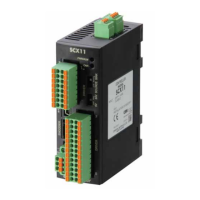
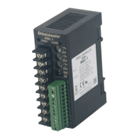
Details the names and functions of the speed controller's components and indicators.

Safety precautions

Precautions for use

Installation

Location for installation

Specifies the ideal environmental conditions and location requirements for installing the speed controller.

Installation method

Details the procedure for mounting the speed controller onto a DIN rail and securing it.

Installing an external potentiometer (Sold separately)

Provides instructions and diagrams for installing an optional external potentiometer.

Installing and wiring in compliance with EMC Directive

Explains methods for installation and wiring to meet EMC Directive requirements for electromagnetic compatibility.

Connection

Connection example

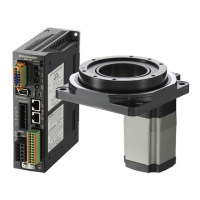
Provides a detailed wiring diagram for connecting the motor, power supply, and control DC power.

Basic operations

Run;stop

Explains how to start, stop, and instantaneously stop the motor using input signals.

Setting the operating speed

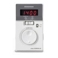
Details methods for setting motor speed using internal potentiometer, external potentiometer, or DC voltage.

Setting the acceleration time and deceleration time

Covers adjusting acceleration and deceleration times for smooth motor operation.

2-speed operation

Describes how to perform two-speed operation by switching between internal and external speed settings.

Timing chart

Presents timing charts illustrating signal sequences for motor operation and speed changes.

Multi-motor control

Explains how to operate multiple motors at the same speed using a single external potentiometer.

Repeated cycle of operation;instantaneous stop

Provides guidelines for motor operation in short cycles to prevent overheating.

Braking current at instantaneous stop

Lists braking current values for different motor outputs during instantaneous stops.

Alarms

Inspection

Troubleshooting and remedial actions

Overview

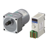
The Oriental Motor MSC-1 is a speed controller designed for the velocity adjustment of AC speed control motors, ranging from 6 to 90 W. It is recognized by UL and bears the CE Marking, complying with both the Low Voltage Directive and EMC Directive under EN Standards.

Function Description

The MSC-1 allows for precise control over motor speed, acceleration, and deceleration. It supports various methods for setting the operating speed, including an internal potentiometer, an external potentiometer (sold separately), and an external DC voltage. The controller also features inputs for forward (FWD) and reverse (REV) operation, enabling clockwise and counterclockwise rotation. It can perform 2-speed operations by switching between internal and external speed settings.

Key operational features include:

  • Run/Stop Control: The motor rotates at the set speed when FWD or REV input is ON. Turning these inputs OFF causes the motor to coast to a stop. Simultaneous ON input for FWD and REV results in an instantaneous stop.
  • Speed Setting: The operating speed can be set from 90 to 1400 r/min at 50 Hz or 90 to 1600 r/min at 60 Hz.
    • Internal Potentiometer (VR1): A precision screwdriver is used to adjust the internal potentiometer, increasing speed clockwise. Factory setting is 0 r/min.
    • External Potentiometer: An external potentiometer (sold separately) can be connected to CN1. When the INT/EXT input is ON, the external potentiometer is enabled, and turning it clockwise increases speed.
    • External DC Voltage: The speed can be set using an external DC voltage (0 to 5 VDC or 0 to 10 VDC). A switch (SW1-1) selects between 5 VDC (OFF position) and 10 VDC (ON position).
  • Acceleration/Deceleration Time Adjustment: Potentiometers VR2 (acceleration) and VR3 (deceleration) allow adjustment of these times from approximately 0.3 to 15 seconds (at 1000 r/min, no inertial load). This helps prevent shock to the load during start, stop, or speed changes.
  • 2-Speed Operation: The controller supports two-speed operation by switching the INT/EXT input, allowing use of both internal and external speed settings.
  • Multi-Motor Control: Up to 20 MSC-1 units can be controlled at the same speed using a single external potentiometer or DC voltage source. Specific resistor connections are required for individual motor speed adjustments in multi-motor setups.

Important Technical Specifications

  • Applicable Motors: AC speed control motors (6 to 90 W).
  • Power Supply: Single-phase 100/110/115 V or 200/220/230 V.
  • Control DC Power Supply: 24 VDC ±10%, 100 mA or more.
  • Operating Ambient Temperature: 0 to +50 °C (non-freezing).
  • Operating Ambient Humidity: 85% or less (non-condensing).
  • Installation Conditions (EN Standard):
    • For use as a component within another device.
    • Protection against electric shock: Class II.
    • Overvoltage category: II.
    • Pollution degree: 2.
    • For overvoltage category III, power must be supplied via an insulated transformer.
    • For pollution degree 3, the speed controller must be stored in an IP54-compliant enclosure.
  • EMC Standards: EN 55011 Group 1 Class A, EN 61000-6-4 (EMI); EN 61000-6-2 (EMS).
  • Cable Sizes:
    • Main circuit (TB1): AWG18 (0.75 mm²) or more (AWG20 to 14 for capacitor connection).
    • Control circuit (CN1): AWG24 to 16 (0.2 to 1.25 mm²).
    • Motor cable extension: AWG18 (0.75 mm²) or more, up to 10 m (32.8 ft.).
    • Rate generator lead wires extension: Shielded cable.
    • Control cable: Braided shielded cable of AWG24 (0.2 mm²) or more, less than 2 m (6.6 ft.).
  • Terminal Block Screw Sizes: M3 for TB1, M2 for CN1.
  • Tightening Torques: 0.8 N·m (7.0 lb-in) for TB1, 0.33 N·m (2.9 lb-in) for CN1.
  • Output Signals: Transistor/open-collector outputs for SPEED-OUT (12 pulses per motor output shaft revolution) and ALARM-OUT (normally closed signal when an alarm generates). Current-limiting resistors are required for these outputs (e.g., 3.3 kΩ to 3.9 kΩ for SPEED-OUT at 24 VDC, 820 Ω to 3.9 kΩ for ALARM-OUT at 24 VDC).
  • Braking Current (Peak Value) at Instantaneous Stop: Varies by motor output power and voltage (e.g., 29 A for 90 W at 100/110/115 V, 13 A for 90 W at 200/220/230 V).
  • Fuse Rating: Single-phase 100/110/115 V: 10 A; Single-phase 200/220/230 V: 6.3 A (Littelfuse, Inc. 216 Series or equivalent).

Usage Features

  • Ease of Installation: Designed for DIN rail mounting (35 mm wide). Requires adequate ventilation space around the unit.
  • External Potentiometer Installation: Detailed instructions for mounting an accessory external potentiometer, including torque specifications for screws and nuts, and soldering guidelines for lead wires.
  • EMC Compliance: Guidelines for wiring and installation to meet EMC Directives, including using mains filters, ferrite cores, shielded cables, and proper grounding techniques. Power cables should be kept separate from control cables with a minimum clearance of 100 mm.
  • Repeated Cycle Operation: Specifies recommended operation/standstill cycles to prevent motor overheating, varying by motor wattage (e.g., 2 seconds for 6-40 W, 4 seconds for 60-90 W).
  • Alarm System: An ALARM LED blinks to indicate specific alarms (e.g., motor lock, motor overheat). The number of blinks corresponds to the alarm type. An ALARM-OUT signal also turns OFF when an alarm occurs.
  • Alarm Reset: Alarms can be reset by turning the ALARM-RESET input ON for at least 10 ms or by cycling the control DC power. Alarms cannot be reset if FWD or REV input is ON.

Maintenance Features

  • Periodic Inspections: Recommended after each motor operation. Checks include cable integrity (scratches, stress), clear openings in the speed controller, and tightness of terminal screws.
  • Troubleshooting Guide: Provides a table of common phenomena (e.g., motor not operating, speed not changing, unstable operation) with possible causes and remedial actions.
  • Semiconductor Elements: Users are cautioned to handle the speed controller carefully due to its semiconductor elements, which can be damaged by static electricity.
  • Disposal: Product must be disposed of correctly in accordance with local laws and regulations.

Oriental motor MSC-1 Specifications

General IconGeneral
BrandOriental motor
ModelMSC-1
CategoryController
LanguageEnglish

Related product manuals