−
6
−
Installation
4 Installation
This chapter explains the installation location, installation methods and measures against noise of the
speed controller.
4.1 Location for installation
The speed controller is designed and manufactured to be installed within another device. Install it in
a well-ventilated location that provides easy access for inspection. The location must also satisfy the
following conditions:
• Inside an enclosure that is installed indoors
• Operating ambient temperature 0 to +50 °C
[+32 to 122 °F] (non-freezing)
• Operating ambient humidity 85% or less
(non-condensing)
• Area that is free of explosive atmosphere or
toxic gas (such as sulfuric gas) or liquid
• Area not stored combustible materials
• Area not exposed to direct sun
• Area free of excessive amount of dust, iron
particles or the like
• Area not subject to splashing water (rain, water
droplets), oil (oil droplets) or other liquids
• Area free of excessive salt
• Area not subject to continuous vibration or
excessive shocks
• Area free of excessive electromagnetic noise
(from welders, power machinery, etc.)
• Area free of radioactive materials, magnetic elds
or vacuum
• Altitude Up to 1000 m (3300 ft.) above sea level
Note
If the ambient temperature of the speed controller exceeds the upper limit of the operating
ambient temperature, revise the ventilation condition or forcibly cool the area around the
speed controller using a fan in order to keep within the operating ambient temperature.
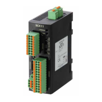
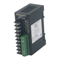
4.2 Installation method
Use a DIN rail 35 mm (1.38 in.) wide to mount the speed controller.
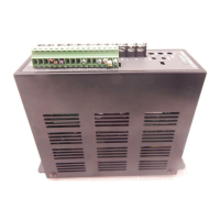
The speed controller is designed so that heat is dissipated via air convection. Provide spaces so that the
speed controller can be ventilated well through its top and bottom vent holes.
Push down the speed controller's DIN lever until it locks. Hang the hook at the rear to the DIN rail, and
push in the speed controller. After installation, x the both sides of the speed controller with the end
plate.
Hook
End plate
Removing from DIN rail
Pull the DIN lever down until it locks using a at tip screwdriver, and lift the
bottom of the speed controller to remove it from the rail.
Use force of about 10 to 20 N (2.2 to 4.5 lb.) to pull the DIN lever to lock it.
Excessive force may damage the DIN lever.
 Loading...