Do you have a question about the Orion Cobalt CO5001 and is the answer not in the manual?
Details the functions and labels of the amplifier's input connectors and controls for setup.
Identifies and explains the amplifier's output connectors and status indicators.
Presents technical performance data for both CO5001 and CO8001 amplifier models.
Details amplifier input section, gain adjustment, and phase controls for optimal integration.
Explains auxiliary outputs for system expansion and the capabilities of the internal crossover.
Specifies fuse sizes, wire gauge, and connection procedures for the amplifier's power supply.
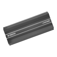
This document serves as an owner's manual for the Orion Cobalt CO5001 and CO8001 power amplifiers, designed for high-performance car audio systems. The manual provides comprehensive instructions for installation, setup, operation, and troubleshooting, ensuring users can achieve optimal sonic results and component reliability.
The Orion Cobalt CO5001 and CO8001 are single-channel Class A/B power amplifiers, engineered to deliver robust audio performance in automotive environments. These amplifiers are equipped with a built-in, fully variable low-pass crossover, making them ideal for driving subwoofers. The CO5001 offers a maximum power output of 500 Watts into a 2-ohm load, while the CO8001 delivers up to 800 Watts into a 2-ohm load. Both models feature a remote gain function, allowing for convenient bass level control from the vehicle's front.
The amplifier's input section is designed for versatility, accommodating various system configurations. It includes RCA inputs for connecting to a source unit, preamplifier, or equalizer, as well as high-level inputs that can connect directly to speaker outputs from a factory radio. The high-level inputs feature an auto-sense signal detection, which automatically turns the amplifier on when a signal is present and off after one minute without a signal, simplifying integration with factory systems.
A key feature is the phase control switch, which allows for adjustment of the output phase (0° or 180°). The 0° setting leaves the output signal in phase with the input, while the 180° setting inverts the output. This phase inversion is particularly useful for optimizing the staging of subwoofers in a vehicle or when bridging two amplifiers into a single speaker.
The internal crossover section is continuously variable and highly flexible, allowing users to fine-tune the low-pass frequency from 50Hz to 500Hz with a 2nd order (12dB per octave) slope. This enables precise control over the frequency range sent to the connected speakers, ensuring that subwoofers reproduce only the desired low frequencies. Additionally, a bass boost switch provides adjustable bass gain in three steps (0dB, 6dB, and 12dB), allowing users to enhance the low-frequency impact of their audio system.
Auxiliary RCA outputs are provided for easy system expansion, allowing multiple Orion Cobalt amplifiers to be daisy-chained without signal loss or overloading the source unit. This buffer stage maximizes signal output and minimizes potential system noise, facilitating complex multi-amplifier setups.
The manual emphasizes a step-by-step installation process to ensure proper setup and optimal performance. Users are guided through choosing appropriate mounting locations, considering factors like ventilation and protection from elements. The low-profile design of the amplifiers makes under-seat mounting possible, provided there is at least 1 inch of clearance for adequate cooling. For trunk installations, mounting the amplifier with maximum clearance around the heatsink is recommended to benefit from convection cooling.
Wiring instructions are detailed, covering power, ground, remote turn-on, and speaker connections. The amplifiers accept up to 4 AWG power and ground wires, with recommendations for optimal performance. A fuse holder must be connected to the battery within 18 inches of the terminal, and the amplifier should be grounded to a good chassis ground as close as possible. The REM terminal connects to the source unit's remote turn-on lead, providing +12V power to activate the amplifier.
Speaker wiring diagrams illustrate connections for single 2Ω speakers or two 4Ω speakers, highlighting the mono nature of the amplifiers and their internal parallel speaker connectors. For advanced configurations, the manual explains how to bridge two identical amplifiers into a single speaker load. This involves setting the phase switch on the "slave" amplifier to 180° while the "master" amplifier remains at 0°, and specific wiring instructions are provided to ensure correct impedance and phase alignment.
The setup and troubleshooting section guides users through initial system testing. This includes checking all wiring connections, setting tone controls to flat, and adjusting amplifier level controls to minimum before powering on the system. Users are instructed to slowly increase the source unit's volume, listening for clear, undistorted output. If distortion or no sound is heard, troubleshooting tips are provided to diagnose common issues such as low remote turn-on voltage, blown fuses, loose connections, or incorrect crossover settings.
Adjusting the sound of the system involves fine-tuning the input gain and crossover settings. Users are advised to select music with high dynamic content that they are familiar with. The source unit's volume control should be set to its highest undistorted output level, typically between 3/4 and full volume. Amplifier level controls for midrange, tweeter, and woofer outputs are then adjusted incrementally until slight distortion is heard, then backed off slightly for an undistorted sound. This iterative process ensures optimal balance and clarity across the frequency spectrum. The remote bass gain control (RGC-2) can be used to match the bass output of the woofer to the system's sonic requirements.
The manual emphasizes several precautions to ensure the longevity and reliability of the amplifier. Users are warned against cutting or drilling into critical vehicle components like gas tanks, fuel lines, or electrical wiring during installation. Disconnecting the vehicle's ground wire at the battery before making or breaking power connections is a crucial safety measure.
Proper mounting is essential; the amplifier must be securely mounted to prevent damage or injury in case of an accident. It should never be mounted where it might get wet or in the engine compartment, as it is not designed to withstand harsh exterior elements. Wires should be routed carefully to avoid scraping, pinching, or damage, and kept away from factory electrical wires to prevent induced system noise.
Fuse replacement is a key maintenance aspect. Users are instructed to replace blown fuses with the same size ATC/MAXI type fuse that came with the amplifier. Using a higher current fuse can damage the amplifier and void the warranty. The manual also highlights the importance of adequate ventilation, as Orion Cobalt amplifiers generate heat during normal operation. Ensuring the area around the amplifier is unobstructed prevents thermal shutdown and potential damage to the unit or surrounding items.
Regular checks of wiring connections for security and correctness are recommended to prevent performance issues and ensure continuous trouble-free operation. In case of thermal protection engaging, improving ventilation around the amplifier is the suggested action. For distorted output, readjusting the gain and checking speaker impedance load are advised. If speakers are blown or wired with incorrect polarity, these issues should be addressed promptly to restore proper sound quality. The manual also provides guidance on resetting crossovers if poor bass response is observed.
| Channels | 1 |
|---|---|
| Bass Boost | 0 - 18dB |
| Subsonic Filter | 10Hz - 50Hz |
| RMS Power at 4 Ohms | 500W |
| Fuse Rating | 120A |