50
Installation
Wiring Work
■Setting Up to Use Remote Operation and External Signals
The product accepts input of a remote-control drive signal, and generates output of a drive signal and
alarm signal. If you wish to use these signals, please refer to the specifications below and connect up
the wiring accordingly. Terminals should be fixed with M3.5 screw hardware.
1. Signal specifications are as follows.
Remote-Control Input
・
Non-voltage contact input (toggle switch)
・
Maximum cable length : 20m
・
Maximum impedance when shorted : 1kΩ
・
Minimum impedance when open : DC11V ~ 18V
・
Inflow current : Approx. DC10mA ~ 17mA
Signal Output
・
Relay Output :“a” (normally-open) contacts
・
AC250V/DC30V 3A (resistance load)
・
Minimum allowable current (reference value) DC5V
10mA
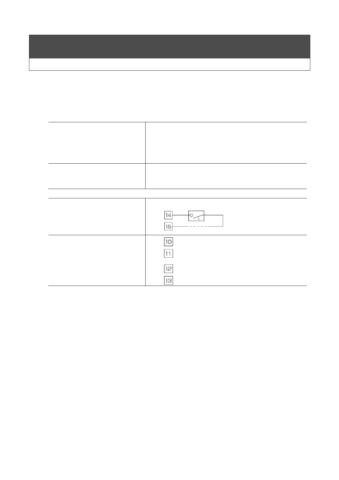
2. Terminal specifications are shown below.
Remote-Control Terminals
Signal-Output Terminals Remote Operation
Operation signal
(Closed when cooler is running.)
Alarm signal
(Closed to indicate ALARM condition.)
Remote Operation
 Loading...