55
Control circuit
※ □ = terminal number, ○ = wire number.
E02
E01
Yellow
Blue
M3
3
CN2
3
1
1
3
CN8
2
1
2
1
CN7
5
2
1
4
7
5
3
1
CN6
K4
K3
CN5
9
7
5
3
CN1
K1
K2
CN4
CN3
1
C
PRS
OLP
THR
M2
M1
THR
MC
E
T
S
R
Red
5
4
2
1
A1/a
F1,2
THR
OLP
MC
M3
M2
M1
STS
WTS
K1〜4
C
SK
PRS
WTS
R1
SK
MC
F2(1A)
F1(1A)
AC200V 50 / 60Hz
Electromagnetic switch for M1, M2
Water temperature sensor
Relay
Running capacitor for M2
Connector
High pressure switch
Fuse
Overcurrent relay for M1
Overload protector for M1
Motor (Circuretion pump)
Motor (Fan motor)
Motor (Compressor motor)
・Open circuit voltage (Voc) : DC 11 〜 18 V
・Short circuit current (Isc) : 10 〜 17 mA
・Input resistance : 1kΩ
・Maximum cable length : 20m
・No-voltage contacts input (alternate switch)
2.Remote operation input specifications
(for reference only) DC 5V, 10mA
・Minimum operation current
・AC250V / DC30V, 3A (resistance load)
・Relay output A contacts (normally OFF)
1. Warning signal output specifications
Wiring by user
terminal block
Remote control
(Closed to indicate ALARM condition.)
(Closed when cooler is running.)
Alarm Signal
Operation Signal
Controler
θ>
A2/b
P>
STS
STS
WTS
15
14
16
15
14
13
12
11
10
13
12
11
10
L3L2
L1
T1
V1
W1
U1
CN1〜8
Symbol
SymbolDescription
Description
Spark killer
M1 intake temperature sensor
Wiring Diagram
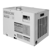
RKS400F1
 Loading...