MSG-A • MSG-D OPERATOR INSTALLATION GUIDE
- 4 -
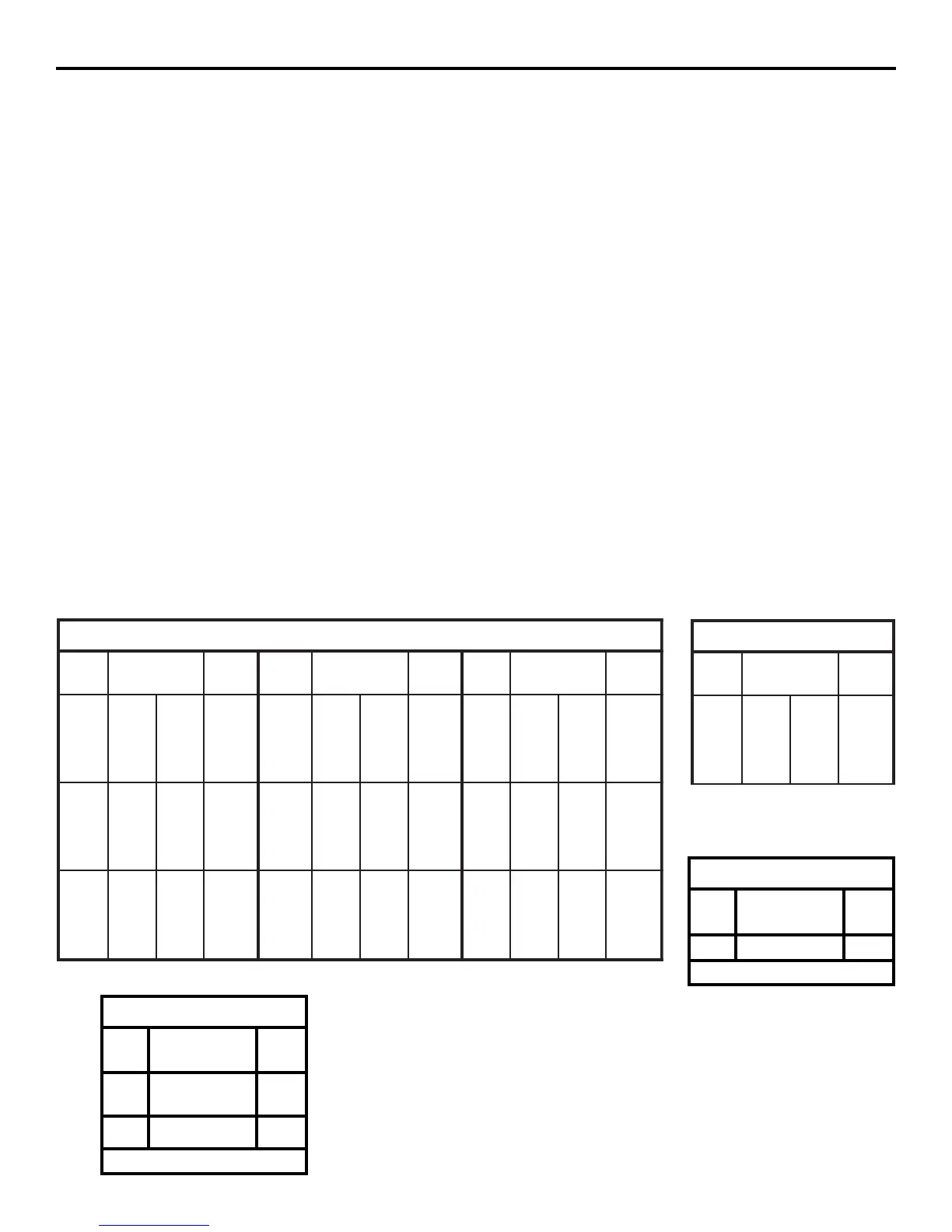
USE COPPER WIRE ONLY!
MODEL MSG-A
gniriWrewoP
stloV
PH&
ecnatsiDxaM
lauDelgniS
eriW
eguaG
stloV
PH&
ecnatsiDxaM
lauDelgniS
eriW
eguaG
stloV
PH&
ecnatsiDxaM
lauDelgniS
eriW
eguaG
V511
2/1
PH
222
453
665
009
0341
111
771
382
054
517
21
01
8
6
4
V802
2/1
PH
067
0021
4291
0603
4684
083
006
269
0381
2342
21
01
8
6
4
V032
2/1
PH
498
2241
4622
0063
4275
744
117
2311
0081
2682
21
01
8
6
4
V511
4/3
PH
871
282
054
617
0411
98
141
522
853
075
21
01
8
6
4
802
4/3
PH
406
859
6251
4242
6583
203
874
367
2121
8291
21
01
8
6
4
V032
4/3
PH
017
8211
6971
2582
8354
553
465
898
6241
9622
21
01
8
6
4
V511
PH1
061
452
604
646
6201
08
721
302
323
315
21
01
8
6
4
V802
PH1
445
468
4731
4812
6743
272
234
686
2901
8371
21
01
8
6
4
V032
PH1
046
6101
6161
0752
0904
023
805
808
5821
5402
21
01
8
6
4
MODEL MSG-D
gniriWrewoP
stloV
PH&
ecnatsiDxaM
lauDelgniS
eriW
eguaG
V511
2/1
PH
079
2451
2542
8983
0026
584
177
6221
9491
0013
21
01
8
6
4
1-02-10
** Due to the nature of motor requirements, secondary circuits, and controls,
208V operators are severely limited in run distance. Exceeding these rec-
ommended distances could lead to frequent maintenance and motor failure.
MODEL MSG-D
ACCESSORY WIRING
All DC Models
24VDC
*Over 350 ft. use DC power.
0-2000
14
Volts
Maximum
Distance (ft.)
Wire
Gauge
MODEL MSG-A ACCESSORY WIRING
All Models
24VDC
*Over 350 ft. use DC power.
0-2000
14
24VAC
250
350*
14
12
Volts
Maximum
Distance (ft.)
Wire
Gauge
1. Select from the chart at the bottom of this page corre-
sponding to the model, voltage and horsepower rating of
your operator.
2. The distance shown on the chart is measured in feet from
the operator to the power source. DO NOT EXCEED THE
MAXIMUM DISTANCE. These calculations have been
based on standard 115V and 230V supplies with a 10%
drop allowable. If your supply is under the standard rating,
the runs listed may be longer than what your application
will handle, and you should not run wire too near the up-
per end of the chart for the gauge of wire you are using.
3. When large-gauge wire is used, a separate junction box
(not supplied) may be needed for the operator power con-
nection.
4. All control devices are now 24VDC, which can be run con-
siderable distances.
5. Wire run calculations are based on the National Electrical
Code, Article 430 and have been carefully determined
based on motor inrush, brake solenoids, and operator re-
quirements.
WIRING SPECIFICATIONS
6. Connect power in accordance with local codes. The green
ground wire must be properly connected.
7. Wire insulation must be suitable to the application.
8. Control wiring must be run in a separate conduit from power
wiring. Running them together may cause interference and
faulty signals in some accessories.
9. Electrical outlets are supplied in all 115VAC models for
convenience with occasional use or low power consump-
tion devices only. If you choose to run dedicated equip-
ment from these devices, it will decrease the distance for
maximum run and the charts will no longer be accurate.
10. A three-wire shielded conductor cable is required to con-
nect master and slave operators. You must use Belden
8760 Twisted Pair Shielded Cable (or equivalent) only –
OSCO part number 2500-1982, per foot). See page 10 for
details of this connection, as well as dip switch selection.
Note: The SHIELD wire should be connected in both
the master and slave operators.