MSG-A • MSG-D OPERATOR INSTALLATION GUIDE
- 9 -
ELECTRICAL CONNECTION AND ADJUSTMENTS
All OSCO gate operators are supplied with a power disconnect switch to turn on and off the power supply available to the
operator. Incoming power should be brought into the operator and connected to the labeled pigtails in the disconnect box,
following wiring specifications on page 4. A wiring connections print can be found on the inside cover of the operator.
Proper thermal protection is supplied with the operator. The motor contains a thermal overload protector to protect from overheat-
ing the motor due to overload or high-frequency operation. This overload will reset automatically after the motor cools down.
LIMIT CAM ADJUSTMENTS
The limit cams are not preset at the factory and must be adjusted for the length and opening angle of the gate the operator is
installed on. The limit switches are activated by a series of rotating limit cams which are attached to the drive shaft. The operator
has also been preset in the right hand operation mode. If the installation requires left hand operation a dip switch must be flipped
(see page 10).
With the gate connected to the gate operator in a mid-travel position, the power disconnect switch turned OFF, and the torque
limiter set loose enough to slip freely, manually move the gate to its fully open position.
Once the gate is in the fully open position, adjust the limit cam for open direction. Set the LSO-1 limit cam so that it has just
triggered its switch.
Once the open limit cam is set, repeat the above process for the close direction, LSC-1.
After finishing the initial limit cam adjustments, reposition the gate to approximately the center of travel. At this time, adjust the
torque limiter as explained on page 8. Turn the power disconnect switch ON, stand clear of any moving parts and press the
OPEN button. Observe the gate as it runs through a complete cycle in both directions, and adjust your limits again if necessary.If
the operator stops during travel, you may need to adjust the open or close current sensor adjustment or the maximum run timer
(see page 12).
Power supply must be of correct voltage and phase.
Always disconnect power from operator before servicing.
Keep clear of gate during operation.
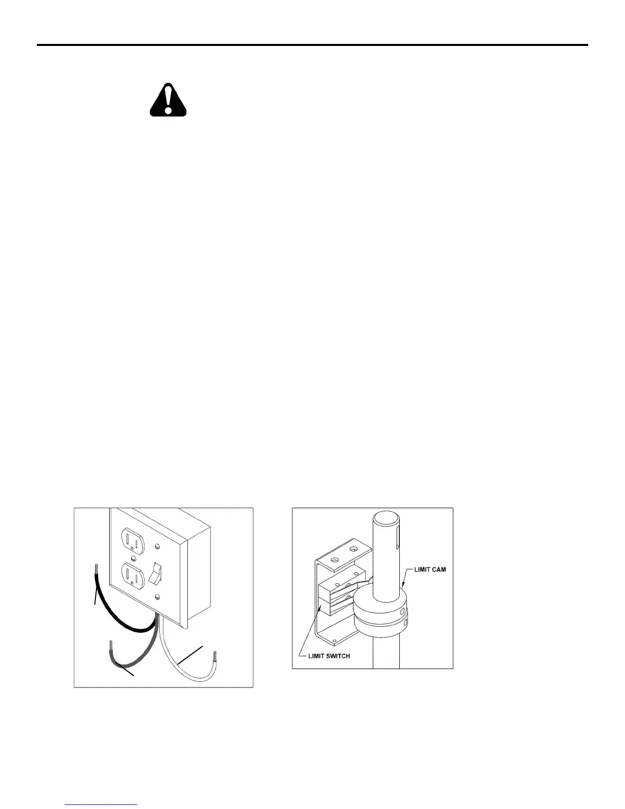
POWER DISCONNECT BOX
(115VAC VERSION SHOWN)
L1
(WHITE)
L2
(BLACK)
GROUND
(GREEN)
LIMITS and CAMS
MODELS MSG-A and MSG-D
FROM TOP TO BOTTOM:
LEFT HAND RIGHT HAND
LSC-1 LSO-1
LSO-1 LSC-1
WHENEVER HAND OF OPERATION CHANGES, BOTH LIMIT CAMS WILL
NEED ADJUSTMENT.
9-13-02