appropriate Subwoofer + and - terminals. Be sure there are no loose strands that can cause
While observing proper wire polarity, connect the Sub OUT of the SMP200 to the
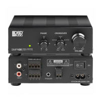
SUB OUT (SMP200)
SPEAKER LEVEL OUT (SMP200)
SPEAKER LEVEL IN (SMP200)
INPUT (SMP200)
output as an amplified subwoofer channel via the SMP200 Sub OUT.
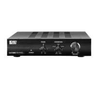
SPEAKER LEVEL INPUT CONFIGURATION
In this configuration, speaker level audio input will passthrough at full bandwidth to the
Speaker Level OUT. It will also be processed by the Crossover, Phase and Volume Controls and
NOTE: Do not connect the AC power cord or turn the amp on until all connections have been
made and confirmed. Making connections with the power on can result in...well...undesir -
able circumstances...that may not be covered under the factory warranty.
1. No connection.
1. Use16AWG (min) 2-conductor stranded speaker wire for speaker connections.
2. Strip approximately 1/2 to 3/4 of an inch off the ends and twist the strands together so
there are no loose strands that can cause shorts.
3. While observing proper wire polarity, connect the Speaker Level OUT of the Audio Amp/
Receiver to the appropriate Speaker Level IN + and - terminals on the SMP. Be su re there
are no loose strands that can cause shorts.
4. Confirm connection and polarity.
1. Use16AWG (min) 2-conductor stranded speaker wire for speaker connections.
2. Strip approximately 1/2 to 3/4 of an inch off the ends and twist the strands together so
there are no loose strands that can cause shorts.
3. While observing proper wire polarity, connect the SMP200 Speaker Level OUT of the SMP200
to the appropriate Left and Right Speaker + and - terminals. Be sure there are no loose
strands that can cause shorts.
4. Confirm connection and polarity.
1. Use16AWG (min) 2-conductor stranded speaker wire for subwoofer connections.
2. Strip approximately 1/2 to 3/4 of an inch off the ends and twist the strands together so
there are no loose strands that can cause shorts.
3.
4.
Confirm connection and polarity.
TRIGGER
1. Using a 2 circuit 3.5mm mini plug, connect +12 to 24VDC from the trigger device to the
striped wire (tip). Connect GND from the trigger device to the unmarked wire (sleeve).
AC MAINS
1. After all connections have been made connect the supplied AC Power Cord to an
unswitched AC power outlet.
shorts.
CONNECTION
 Loading...