11
1. Remove your OSET & Accessory pack from the box and check contents against the
following list:
1x Bike
1x Accessory Box containing:
1x Front mudguard (fender)
1x Baery charger c/w power lead & manual (if supplied)
1x Number board
4x Black cable es
1x Hex Key set (Allen keys)
1x Adjustable Spanner
1x Manual for air forks
1x Manual for rear shock
2. Place your OSET on a solid & level stand, with both wheels o the ground.
UNPACKING AND ASSEMBLY
Failure to properly assemble and adjust your bike prior to use may result in an
accident resulng in death, serious injury and/or property damage. If you are uncertain
about any aspect of the assembly and adjustment of your bike, seek help from a qualied
mechanic or the OSET Customer Service Department.
WARNING!
There are no user serviceable elements incorporated into the motor, motor controller,
baeries, baery charger, throle, or wiring harness of your OSET electric bike. DO NOT
ATTEMPT TO DISASSEMBLE OR ADJUST ANY OF THESE COMPONENTS. Doing so may cause
extensive damage to these components, will void your warranty, and may cause a
hazardous condion. If you cannot resolve a problem using this owner’s manual, contact
your OSET authorized dealer, or call the OSET Customer Service Department for
assistance.
WARNING!
NOTE
If you purchased your OSET at a local retailer your machine may be fully adjusted and ready
to ride. If you purchased your OSET in the carton, please carefully follow the instrucons
below and any supplemental instrucons to nish the assembly and adjustment of your
OSET.
12
3. Remove all the packing materials.
4. Using the supplied Allen keys, make sure the steering stem is in the forward facing
posion and ghten the top and side bolts securely and evenly to 12nm.
Secure the handlebars ghtly in the steering stem. Double check ghtness and
alignment. Adjust the brake lever posions and reach to suit the rider. See page 21.
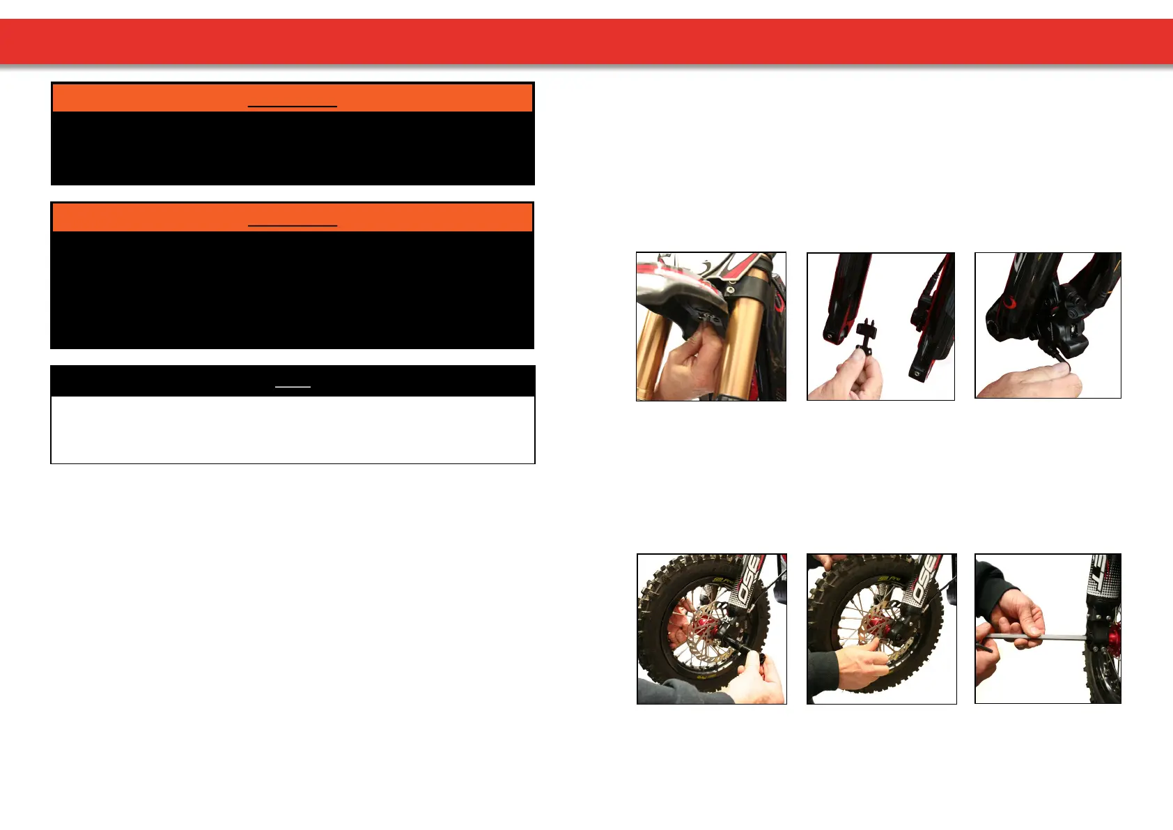
5. Fit front mudguard using the bolt & washers provided (picture 1).
6. Fing Front Wheel.
Remove disk pad spacer (picture 2 - this item is used for transport only, keep this if
you are likely to leave the bike without the front wheel ed).
(1.) (2.) (3.)
7. Loosen top calliper Allen bolts (picture 3 - using 5mm wrench) - so it will move side to
side so as to aid ng of wheel.
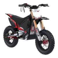
8. With one axle bolt already screwed into the axle, hold the front wheel in the fork
lowers & slide the axle in through the hub. (picture 4 - ensure the pinch bolts on the
front of the forks are already loose).
9. Tighten the two pinch bolts on the side of the fork from which you inserted the axle
(picture 5).
(4.) (5.) (6.)
10. Replace locking bolt on the other side of the axle & ghten (picture 6).
UNPACKING AND ASSEMBLY