13
11. Finally, ghten to remaining two fork pinch bolts on the fork lower.
12. Spin the front wheel and apply the front brake. Do this twice. While holding the front
brake on - ghten calliper bolts. This will centre the calliper and help to give even
wear of the pads and free running of the front wheel.
13. Adjusng rear calliper. Ensure rear wheel is clear of ground and turn by hand and
check brakes are not binding. If they are, loosen cap screws and adjust.
Be aware that because the wheel can be moved back and forth for chain adjustment
the calliper does also - so make sure it does not rub on the outer diameter of disc.
14. Install the front number plate using the supplied ‘zip-es’. This aaches to the
handlebars and the forks (picture 7).
(7.) Zip-es (8.) (9.)
15. Check re pressure of both res and conrm they are properly inated to 20-40 psi.
Light riders can use lower pressures.
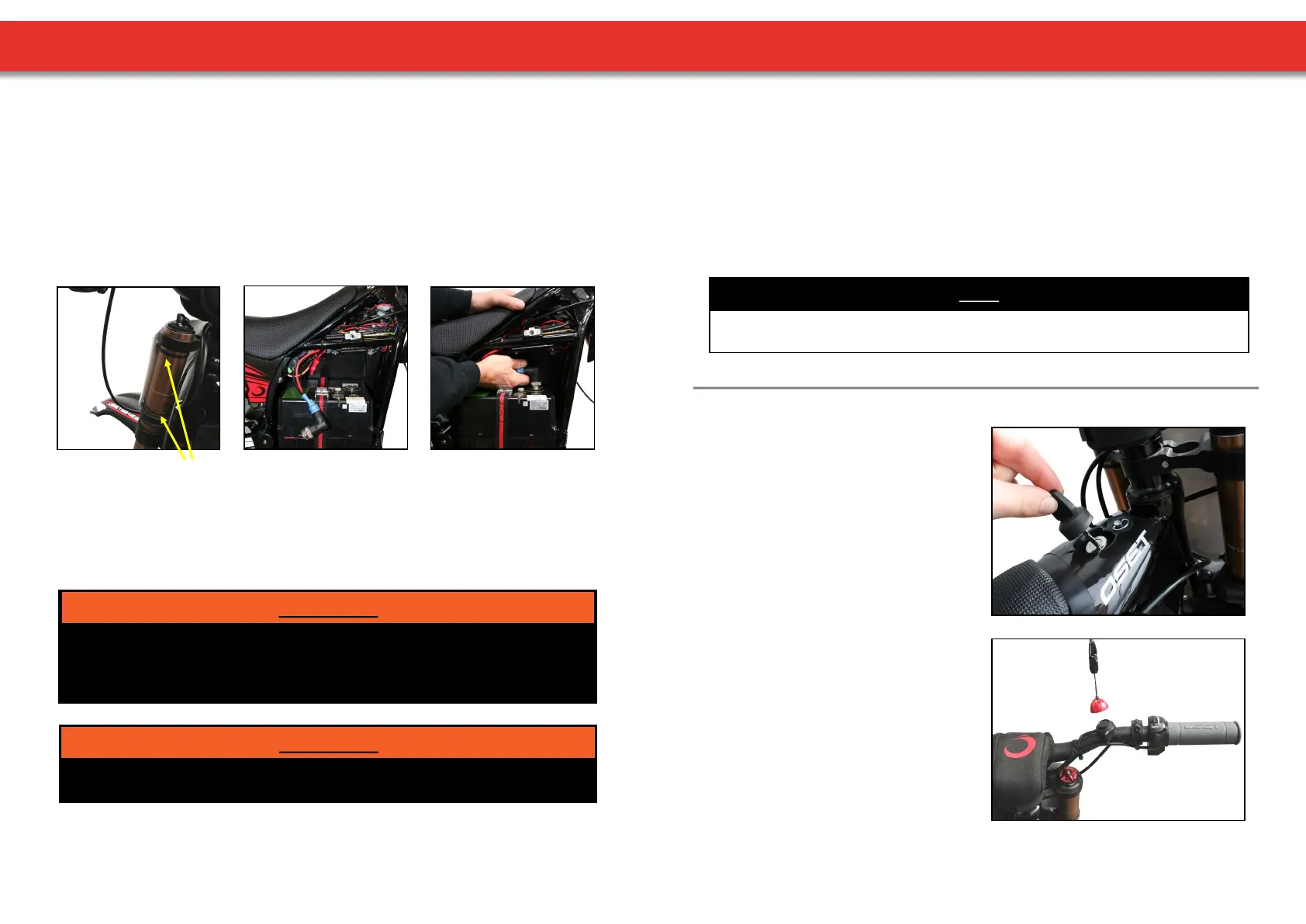
16. The baeries are not connected for shipping purposes and will need connecng. It is
vital that connecons are made correctly. The baery strap should be ed before
connecng the main baery lead. Install the baery as indicated (picture 8 & 9).
Failure to properly install the baeries may result in an accident resulng in death, serious
injury and/or property damage. If you are uncertain about any aspect of the assembly and
adjustment of your bike, seek help from a qualied mechanic or the OSET Customer
Service Department.
WARNING!
17. Unpack charger (if supplied) from its box and read pages 22-25 of this manual.
Charge the baeries while thoroughly reading the rest of this owners manual.
The power must be switched to the o posion before aaching and
plugging in the charger.
WARNING!
UNPACKING AND ASSEMBLY
14
18. Compress and check each brake lever in turn. The lever should not compress
completely to the bar. Each individual brake should hold the bike securely when you
push the OSET against the brake. If your brake needs adjustment, follow the
instrucons on page 21. Learning riders should be aware which lever operates which
brake.
19. For maximum baery life, always fully charge before operang your OSET for the rst
me and never store with discharged baeries. (See page 25 ‘Baery Care &
Maintenance).
20. While your baeries are charging, please Read Your Owners Manual completely.
NOTE
Now your OSET is fully assembled, adjusted and checked. Once the baeries are fully
charged, your OSET will be ready to ride safely.
The key switch turns the power on and o.
When the rider is sing on the bike, this is
located in front of them above the seat
cover.
The key is removable, and should be
removed when the bike is not in use.
KEY SWITCH
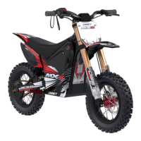
This switch is in addion to the key switch
and provides extra funconality. The key
switch MUST be in the ‘on’ posion for the
magnec kill switch to operate.
With the key switch in the ‘on’ posion, the
kill switch can be used to turn the bike on
and o, simply by connecng the red
magnec cap to the black base on the
handlebar.
As a safety precauon, if the throle is
applied before the kill switch is connected,
the bike will not move.
KILL SWITCH
SWITCHES