24
HYDROFIT™ Owner’s Information Manual
WARNING: The use and ownership of this work is defined in the legend upon the front page hereof.
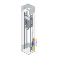
The Plunger and Cylinder Assembly (“Jack”)
The jack assembly raises and lowers the elevator car. The assembly’s components
include two lengths of steel tubing—each a different diameter—called the plunger and
cylinder. The larger diameter tube is the cylinder. The plunger and the hydraulic oil are
inside of the cylinder. The plunger and cylinder are designed to exacting engineering
specifications for your building’s rise, load capacity, and speed requirements.
The plunger tube raises and lowers through the cylinder head. The cylinder head also
wipes the oil from the plunger tube and stops the plunger from rising out of the cylinder.
The length of these components depends on the type of hydraulic arrangement:
HydroFit™ is a holeless type arrangement; the cylinders are mounted to the building’s
foundation (above ground).
If you place your hand into a pail of water, you’ll
observe that the water moves, or is displaced, by
the action. You may also notice the tendency of the
water to resist your hand in the form of force. The
force applied to the resistance of the liquid
produces pressure. Hydraulic pressure lifts the
elevator car. Oil flows from the control valve
through piping and into the sealed cylinder. The oil
in the cylinder is not compressible and pressure
builds up. Eventually, the pressure reaches a level
that overcomes the weight of the plunger and
elevator car (called “gross load”), and pushes the
plunger upwards, lifting the elevator car. The
control valve and size of the motor/pump determine
the speed at which the elevator lifts. Down travel is
controlled by the valve alone; the motor and pump
do not operate.
Oil Monitoring Devices
A number of devices, some optional, help handle the various issues that come up when
using substances such as oil, and machinery like motors and pumps. The following
paragraphs provide you with additional information about your equipment.
Fluid pulsation from the pump transmits through the elevator structure and into the
elevator car. To alleviate this effect, a muffler may be used between the various piping
connections from the control valve to the cylinder. To further compensate for this
disturbance, sound isolation pads are mounted between the oil tank floor and the motor
feet.
This system comes standard with a low-pressure switch. The switch activates if the
pressure in the jack assembly falls below a preset value. Once activated, the switch
prevents the elevator from moving down. If the situation is detected when the elevator car
is traveling down, the system stops the elevator car and then attempts to move it up to the
next available door zone. The switch is mounted in line with the control valve piping.
The low oil level switch, similar in name to the switch mentioned above, is an optional
device. If the oil level falls below a set level, the switch cuts off power to the motor,
thus preventing the elevator from operating. This switch is mounted in the oil tank and
positioned at a point above the pump’s oil inlet line. Otis’ Remote Elevator Monitoring
(REM®) also monitors oil level and notifies Otisline® if the level is too low.
An oil temperature sensor monitors the temperature of the hydraulic oil and makes sure
it is within an acceptable range. If the oil falls below the minimum operating temperature