25
HYDROFIT™ Owner’s Information Manual
WARNING: The use and ownership of this work is defined in the legend upon the front page hereof.
of 90 degrees for six minutes, the system activates an oil recycling operation. The
recycle operation starts the motor pump, which brings the oil back to the tank. The
operation of the motor pump and the friction of the oil from its own natural resistance
to flow causes the oil to heat. A complete cycle period is five minutes on, followed
by 10 minutes off, until the oil reaches 90 degrees. Conversely, an oil temperature
condition above 140 degrees could cause damage to the motor. At this temperature,
the sensor alerts the system to stop operation until the oil temperature is again within
its operating range. When the REM® product is installed, it records any temperature
fault, which your Otis maintenance examiner can use to analyze corrective actions.
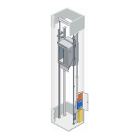
Positioning Equipment
The positioning equipment tells the controller where the elevator car is within the
hoistway. Magnetic strips are placed at exact locations within the elevator hoistway
and sensors designed to “read” these magnetic strips are mounted to the elevator
car. As the elevator moves up and down the hoistway, the sensors activate electrical
signals as they pass the stationary magnetic strips. The signals are sent to the controller.
Each of the magnetic strips generates a unique signal. Your controller knows what
signal to expect from each of the magnetic strips because that information is stored in
memory. The signal tells the controller which floor the elevator is passing or stopped
at, its direction of travel, and whether the elevator car floor is level with the landing
floor. If the car is not level with the floor, it will re-level to compensate for weight
differences as passengers enter and exit.
The physical make-up of positioning equipment includes more than just the magnetic
strips and sensors. Other components include the Reader Tape, Reader Box, Limit/
Stopping Switches. Each is explained in the paragraphs that follow.
The reader tape is actually a thin piece of steel attached to the side of the hoistway rail. It
reaches from the bottom to the top of the hoistway. On it, the magnetic strips that help
the controller determine the position of the elevator are mounted in precise locations.
The reader box contains sensors that “read” the magnetic strips. The reader box is
mounted to the top edge of the elevator car and as the car moves in the hoistway, the
reader box glides over the reader tape. Position signals are generated and sent to the
controller through sensors mounted on a circuit board located inside the box.
The elevator’s positioning function is like that of a road map. If you use the map’s legend
to identify a location, say Main Street, it provides you with the coordinates, e.g., A,1. This
represents the horizontal and vertical markings along the map’s sides. The intersection at
which the coordinates meet is the location point.
Similarly, the elevator has a legend that describes position; in this case stored in
computer memory. As the elevator moves, the sensors and magnetic strips provide
the intersecting information that, when compared to the information in memory,
provides a location.