61
External Communications
All available data parameters are stored in Holding Registers within the multiprobe, which
start counting at 40001. They are addressed in the Modbus message structure with
addresses starting at 0. Modbus function 03 is used to request one or more holding
register values from the multiprobe. Each Holding Register is 16 bits (2 bytes) in size,
therefore two Holding Registers (4 bytes) are required to represent a single floating point
value. Only one slave device can be addressed in a single query. The query structure is
detailed in Table 6. A complete register list can be found at www.hachenvironmental.com.
After processing the query, the multiprobe will return the 16 bit Holding Register values
that were requested. The Holding registers will be transmitted as High Byte first, followed
by the Low Byte. The Modbus response starts with the multiprobe address and the
function code 03. The next byte is the number of data bytes that follow. This value is two
times the number of registers returned. The two byte CRC is appended at the end.
Example: The multiprobe stores pH information at holding registers 40007 and 40008.
These registers are addressed as 0x0006 and 0x0007. The following sequence of bytes
request pH from a multiprobe with slave address 1.
Result: The data is sent Low Word First, High Byte First, therefore the IEEE Floating
Point Formatted value representing the pH is: 0x4106A8C9 = 8.416 Units.
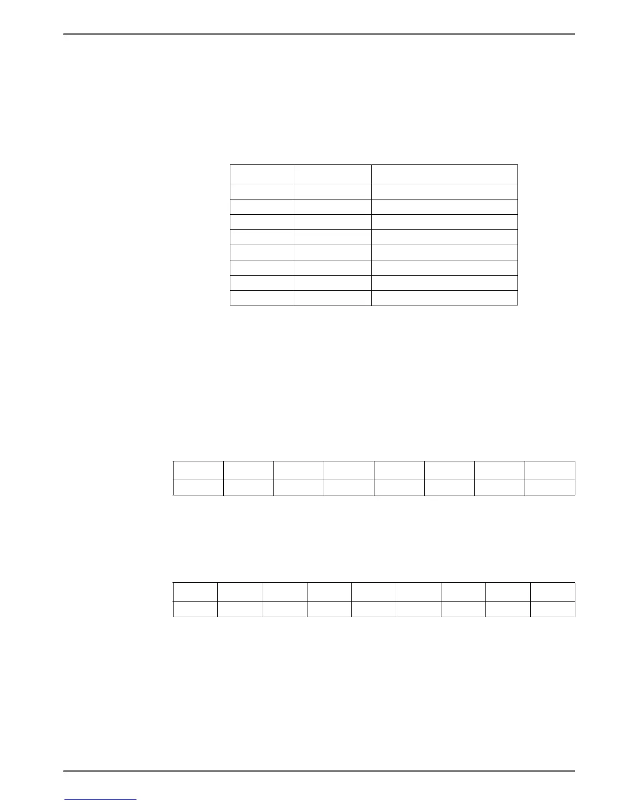
Table 6 Function 03 Query Structure
Byte Value Description
1 1–247 Slave device address
2 3 Function code
3 0–255 Starting address, high byte
4 0–255 Starting address, low byte
5 0–255 Number of registers, high byte
6 0–255 Number of registers, low byte
7 0–255 CRC, high byte
8 0–255 CRC, low byte
pH Query Example:
Byte 1
1
1
Slave Address
Byte 2
2
2
Command 3—Read Holding Register
Byte 3
3
3
Address of the first Holding Register to read (0x0006)
Byte 4
3
Byte 5
4
4
Number of Holding Registers to Read (2 registers—4 bytes)
Byte 6
4
Byte 7
5
5
CRC
Byte 8
5
0x01 0x03 0x00 0x06 0x00 0x02 0x24 0x0A
Response:
Byte 1
1
1
Slave Address
Byte 2
2
2
Command 3—Read Holding Register
Byte 3
3
3
Number of Data Bytes (4 bytes—2 registers)
Byte 4
4
4
pH
Byte 5
4
Byte 6
4
Byte 7
4
Byte 8
5
5
CRC
Byte 9
5
0x01 0x03 0x04 0xA8 0xC9 0x41 0x06 0xBA 0x3F