5.5 Connecting the OTT PLS to any datalogger using an SDI-12
interface
䡵 Connect the OTT PLS to an SDI-12 input of the datalogger. Follow the datalogger
handbook when doing this. Refer to Figure 4 for the wire assignments of the
O
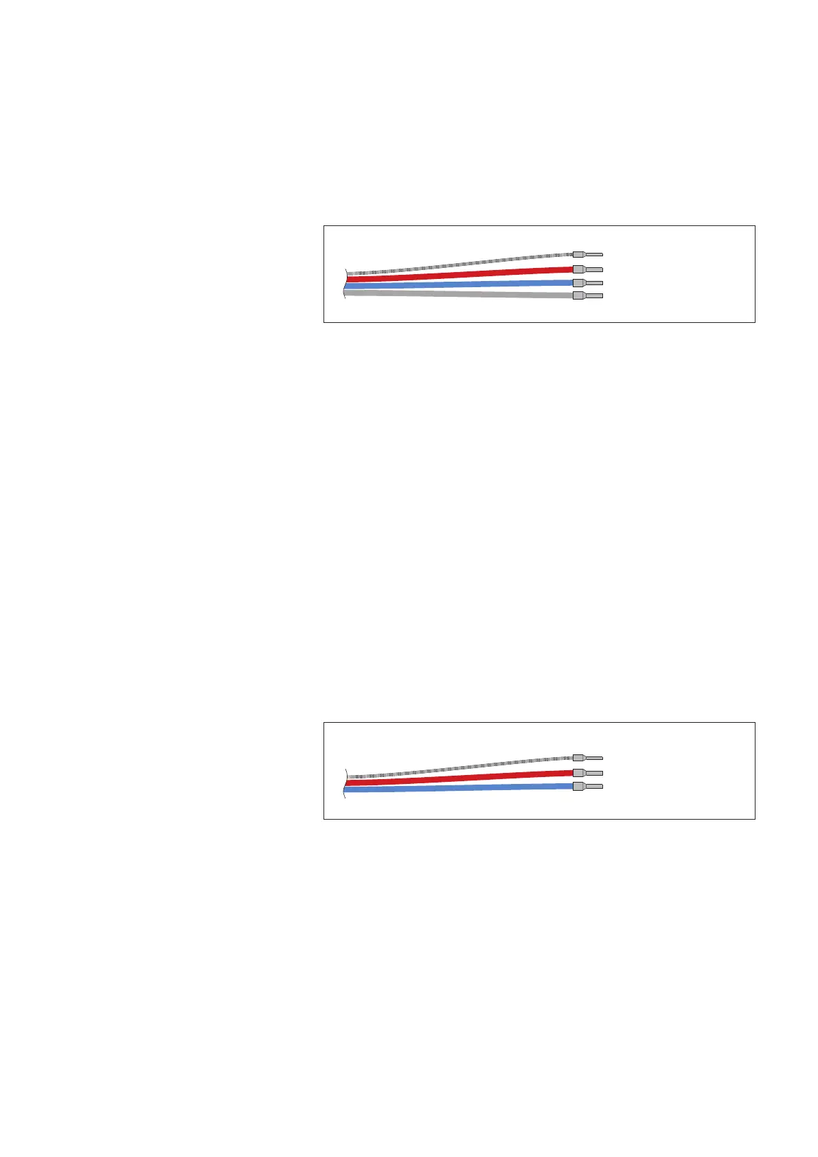
TT PLS. Wires used: red, blue, and gray. The maximum length of the cable is
100 m.
䡵 To achieve better protection against overloads, you can optionally connect the
cable shielding to a grounding point/equipotential busbar.
Note
The standard supply voltage (12 Volt line) in an SDI-12 bus is 12 Volts and the
maximum is 16 Volts. Take this into account if other sensors are available in the
SDI-12 bus in addition to the OTT PLS sensor.
The SDI-12 commands and responses used with the OTT PLS can be found in
Chapter 6, SDI-12-Commands and Responses.
5.6 Connecting the OTT PLS to any datalogger using a 4 … 20 mA
interface
䡵 Connect the OTT PLS to a 4 … 20 mA input of the datalogger. Follow the dat-
alogger handbook when doing this. Refer to Figure 5 for the connection
assignments of the OTT PLS. Wires used: red and blue.
Maximum cable length: dependent on the level of the supply voltage and size
of the burden (load resistor). Ensure that the ohmic resistance of the pressure
probe cable together with any burden present does not exceed the maximum
permitted load resistance (see Chapter 5.7). The upper limit for the cable length
is 1,000 m in all cases.
䡵 To achieve better protection against overloads, you can optionally connect the
cable shielding to a grounding point/equipotential busbar.
5.7 Determining the maximum load resistance at the 4 … 20 mA
interface
The load resistance (burden + ohmic resistance of the connection cable) connected
to the OTT PLS must not exceed a specific maximum value. This value depends on
the level of the supply voltage of the OTT PLS. If the load resistance is greater, the
loop current* can no longer be evaluated. Smaller load resistances are allowed.
* Due to the imposed (controlled) current by the OTT PLS of the 4 … 20 mA interface (=
^
measured value)
Fig. 5: Wires used with a
4 … 20 mA interface.
If the OTT PLS is to be configured via
the RS-485 interface, the green and
orange wires are required in addition.
Cable shielding
+9,6 … 28 V DC (red)
GND (blue)
Cable shielding
+9,6 … 28 V DC (red)
GND (blue)
SDI-12 Data (gray)
Fig. 4: Wires used with an SDI-12 interface.
11