5.2 Installation type B: hanging pressure probe
See also Figure 1.
䡵
Determine the minimum and maximum water level at your station (e.g. staff
gauge, contact gauge). Use both values to specify the probe position. The follow-
ing conditions must be fulfilled:
– position the probe below the minimum water level if possible;
– difference between max. water level and position of the probe < measuring
range of the probe.
䡵 Fix the cable attachment (accessory) at a suitably sized attachment point.
䡵 Carefully lower the pressure probe on the pressure probe cable to the specified
depth. There are markings on the cable every 0.25 m to assist orientation.
䡵 Lay the pressure probe cable in the opened clamping jaws of the cable attach-
ment as shown in Figure 1 and secure the pressure probe cable by pushing the
clamping jaws together. The mechanical longitudinal stability required is pro-
vided by Kevlar fibers inside the pressure probe cable. Caution: maximum
hanging depth: 50 m. (greater depths on request).
Notes
䊳
The fine setting of the probe position is carried out, for example, by entering a
reference or offset value (with SDI-12/RS-485 interface) or using a scaling
function of the datalogger connected. It is thus sufficient in many applications
to position the probe approximately.
䊳
If the pressure probe cable ends in the immediate vicinity of the cable attach-
ment: fix the Kevlar fibers at a suitable point in addition!
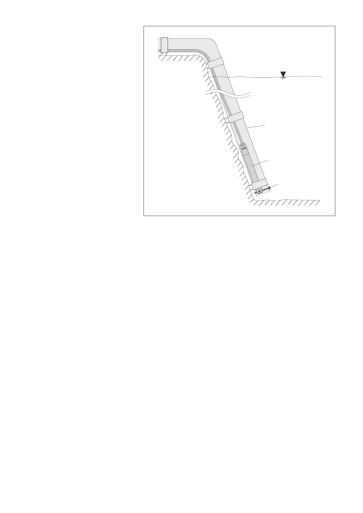
Plastic protective tube
Fixing pin
OTT PLS
Fig. 2: Installation example of the OTT PLS
pressure probe in open waterways.
With waterways with currents or swell, a
fixing pin is used to securely fasten the
probe. Push the fixing pin through the
holes in the black protective cap.
9