Appendix B – Connecting the OTT PLS to an OTT netDL or OTT DuoSens datalogger
using a 4 … 20 mA interface
䡵
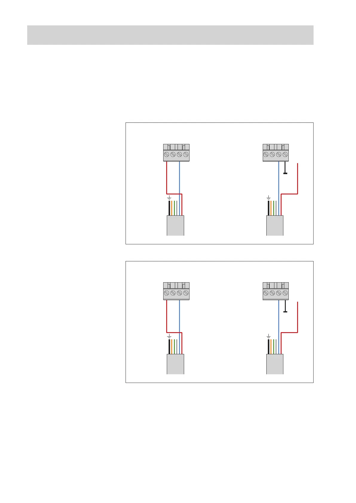
Connect the OTT PLS to the OTT netDL IP datalogger or to the OTT DuoSens
C
ompact Datalogger as shown in Figures 12 and 13. Take note of the operat-
i
ng instructions for the OTT netDL/OTT DuoSens.
M
aximum cable length: dependent on the level of the supply voltage and size
o
f the burden (load resistor). Ensure that the ohmic resistance of the connection
c
able together with any burden present does not exceed the maximum permitted
load resistance (see Chapter 5.7). The upper limit for the cable length is 1,000 m
in all cases.
䡵 To achieve better protection against overload, you can optionally attach the
cable shielding to a ground point/potential equalization panel.
4 … 20 mA
Input
G … K
1)
/ G … M
2)
431 2
OTT netDL
4 … 20 mA
Input
G … K
1)
/ G … M
2)
431 2
OTT netDL
Pressure probe cable
+9.6 … 28 V
I in –
I in +
I in +
I in –
1
)
OTT netDL 500
2
)
OTT netDL 1000
Fig. 12: Connecting the OTT PLS to the
OTT netDL using a 4 … 20 mA interface.
The letters above the screw terminal
strip identify the possible connections
on the OTT netDL..
The supply for the loop current and the
supply of the OTT PLS is made, in the
application example shown, directly from
the OTT netDL.
4 … 20 mA
Input
C … F*
431 2
OTT DuoSens
* only with a OTT DuoSens
with analog extension
4 … 20 mA
Input
C … F*
431 2
OTT DuoSens
Pressure probe cable
+9.6 … 28 V
I in –
I in +
I in +
I in –
Fig. 13: Connecting the OTT PLS to an
OTT DuoSens using a 4 … 20 mA inter-
face.
The letters above the screw
terminal strip identify the possible
connections on the OTT DuoSens.
The supply for the current loop and the
supply of the OTT PLS is made in the
application example shown on the left
directly from the OTT DuoSens.
28