Appendix C – Installing the OTT FAD 5 humidity absorbing system
The OTT FAD 5 humidity absorbing system accessory for the OTT PLS pressure
probe fulfills various functions:
䊳 drying the air that has entered the pressure compensation capillary;
䊳 connecting the pressure probe cable with a connection cable to the data -
logger/electrical supply via several two-pin connectors;
䊳 with short pressure probe cables (< 5 m): it can be used as a fixing point
to hang the OTT PLS.
Requirements of the installation location
䊳 The installation location must be protected from humidity as effectively as possible.
䊳 If the installation location is in a control cabinet: There must be a pressure com-
pensation possibility to the surroundings (no hermetically sealed closure)!
䊳 Installation position only as shown in Figure 15.
䊳 OTT FAD 5 to be used as a fixing point: Attach the humidity absorbing
system over the station so that the pressure probe hangs freely (cable length
OTT PLS < 5 m).
Fasten the OTT FAD 5 as follows:
䡵 Unscrew the four captive screws on the housing lid and remove it.
䡵 Secure the humidity absorbing system on a solid surface with four screws.
Hole spacing: 79 mm. (Select screws appropriate to the material: e.g. wood
screws with plugs, machine screws with nuts, Ø 4 mm.)
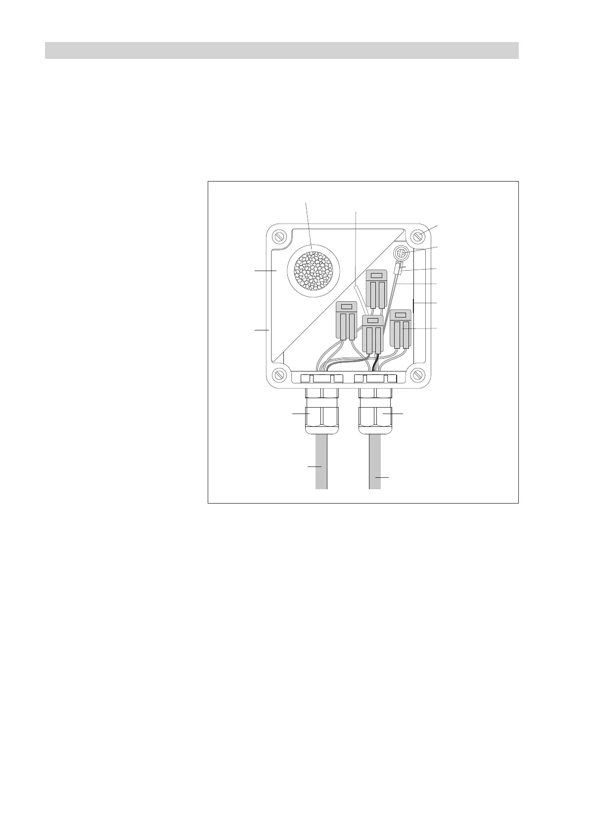
Dessicant cartridge
Ring terminal
OTT FAD 5
Kevlar core
Air-permeable
membrane
Connector
(number
according to
requirements)
Cable gland
(for Ø 4,5 … 10 mm)
Pressure compensation
capillary
Cable gland
(for Ø 4,5 … 10 mm)
Pressure probe cable
OTT PLS
Connection cable
datalogger/
electrical supply
Shaped
foam part
Cross-head
bolt
Attachment bolt
(4 x)
Fig. 15: Installing the OTT FAD 5
humidity absorbing system.
(Housing lid has been removed.)
30