Warning: RISK OF FIRE OR ELECTRIC SHOCK. DO NOT CONNECT THE GPS CONNECTOR DI-
RECTLYTOANANTENNA.
Components
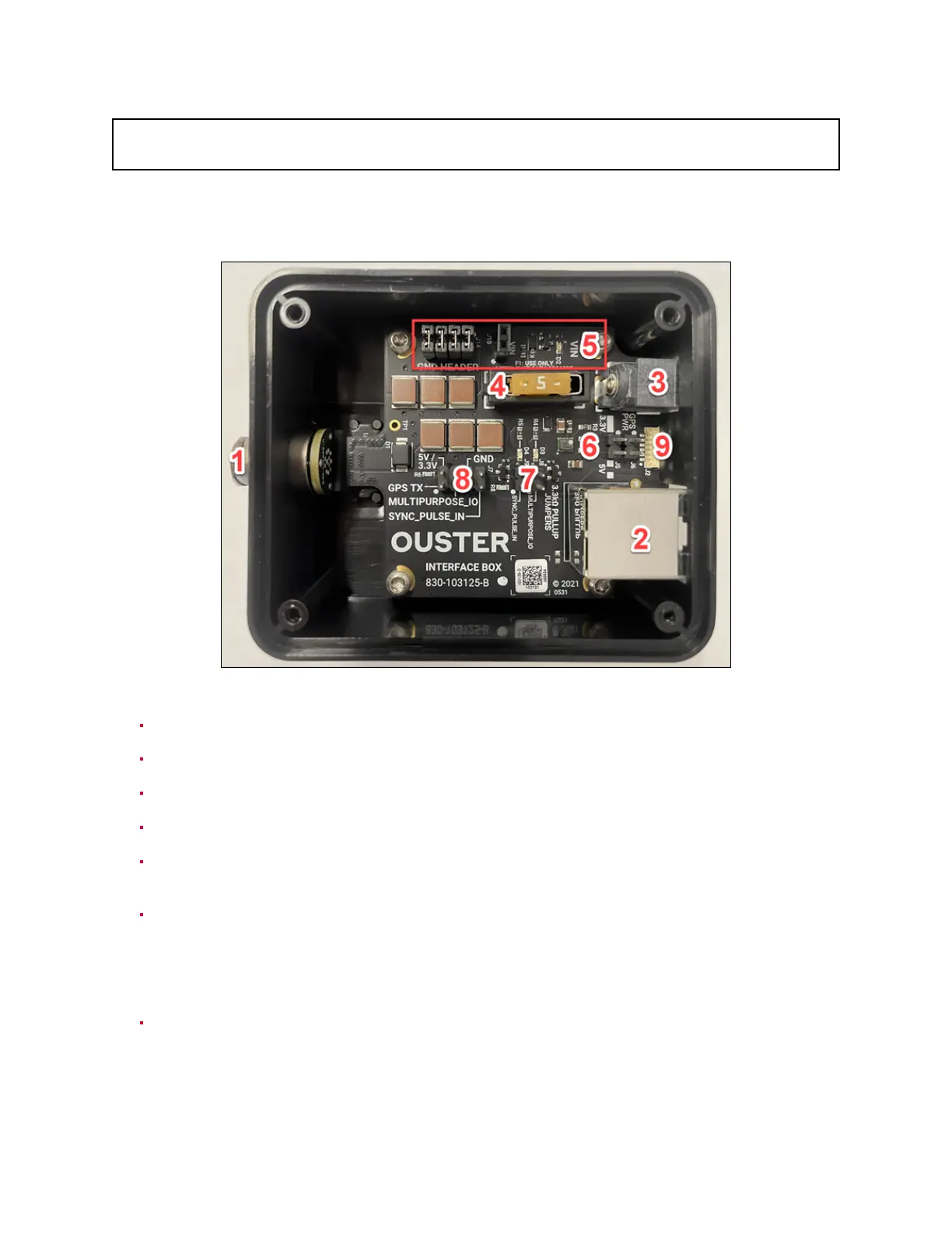
Figure7.2: InterfaceBox Specification
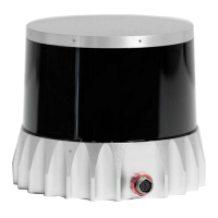
1-Sensorconnector. Connecttothe sensorwithadouble-endedconnectorcable.
2-Ethernetjack. RJ45,gigabitspeed(1000base-T).
3-VINBarrelJack. Usewith a2.5mminnerdiameter,5.5mmouterdiameterbarrelplug.
4-Userreplaceable5Afuse. Use onlyLittlefuse#0891005.
5 - VIN green LED indicator(D2), fuse-protected VIN header (J10) and Ground header / jumper
storage(J14).
6-OnboardMAXM15067buckpoweringVCC_3P3|5. VCC_3P3|5suppliestheonboardLEDsand
pullups,andisuseraccessibleviaheadersJ2&J7. HeaderJ5isusedtoselectthebuck’soutput
voltage: installajumperfor3.3V,leaveopenfor5V.WARNINGS:Maxallowableuserconsumption
is210mA.EnsurepowertotheInterfaceBoxisdisconnectedwhenchangingbuckoutputvoltage
viaJ5.
7 - 3.3kΩ pullups to VCC_3P3|5 and green LED indicators for MULTIPURPOSE_IO and
SYNC_PULSE_IN.Installajumperontherespectiveheader(J8orJ9)toenable thepullup.
18