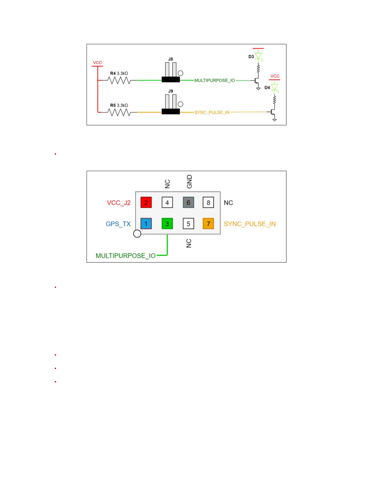
Figure7.3: J8& J9Circuitry
8 - 0.1” pitch, 4x2 pin header J7. GPS_TX (Pin 1) is only connected to connector J2; it is not
connectedtothesensor.
Figure7.4: J7Circuitry
9 - 6-pin JST SH/SR connector J2. VCC_J2 (Pin 2) is connected to VCC_3P3|5 by installing a
jumperon headerJ6. GPS_TX (Pin6) isonlyconnectedtoheaderJ7;it isnot connectedto the
sensor.
Connectors
ConnectivityGuide:
RJ45: Ethernetconnection toacomputer
6-PINJSTSH/SR:GPS connectorport
BarrelJack: 24VDCpowersupply
19