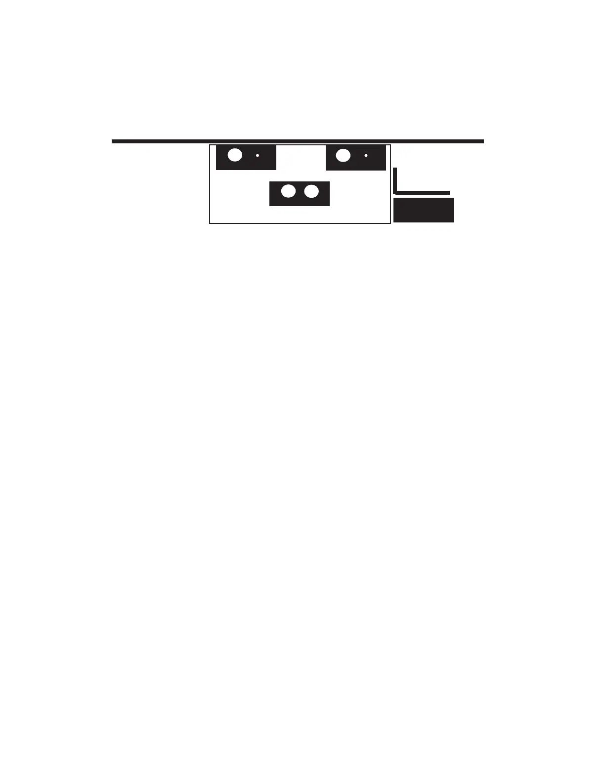
Figure 2 - Three MX60 mounting options on the top of an OutBack PSDC Disconnect Enclosure
4
MOUNTING THE MX60
When wiring the MX60 note that there is a current limit on the output at 60 amps and that the unit is listed to operate
continuously at 60 amps. There is no 80% derating as required by the NEC for fuses, conductors, and most circuit
breakers.
The MX60 is a buck type converter and can not boost the output current when the PV array peak power point voltage is
below the battery voltage as may happen on hot days in 24VDC PV and a 24VDC battery system or a 48VDC PV and a
48VDC battery system.
This unit can supply up to 60 amps output depending on the nominal PV array voltage and the nominal battery voltage.
The output is current limited to 60 amps. To meet minimum NEC requirements, the output conductor should have an
ampacity after any temperature and conduit fill corrections of 1.25 x 60=75 amps (NEC 310.15, 690.8,9). This would
normally indicate that the output conductors would be 4 AWG, but a larger size may be required if there are temperature
and/or conduit fill corrections required. With an output conductor rated at 75 amps (1.25 time continuous output current),
a circuit breaker rated for continuous 100% duty at 60 amps (continuous output) like the OutBack OBDC-60 breaker may
be used to provide the code-required disconnect and output circuit overcurrent protection.
The PV array output connected to the MX60 input may be as high 60 amps, but at this current level, there is very little (if
any) current boosting or maximum power-point tracking due to the 60-amp output current limit. Additionally, the input
current may exceed 60 amps on bright sunny days and any excess power would be lost. The size and ampacity of the
input conductors must be selected to handle 1.56 times the short-circuit current of the PV array. Any disconnect or cir-
cuit breaker
connected to the input conductors must also be rated at 1.56 times the short-circuit current for the PV array unless the
breaker is rated for 100% duty in its enclosure. If that is the case, the circuit breaker may be rated at 1.25 times the PV
array short-circuit current.
WIRE AND DISCONNECT SIZING
A standard 1" TSC threaded nipple may be used to secure the controller to the PSDC top for many installations. All of
the wires will fit through one knockout so the other can be used as a means of attachment. If one knockout is used for
wiring, then drill through and bolt the MX60 to the PSDC top using a #10 (5mm) bolt, lockwashers and nut. The use of a
7/8 inch spacer behind the MX60 when installed in either of the two rear positions will allow the mounting foot holes to
be used to secure the chassis back to the wall.
When mounting the MX in a confined space, be careful not to block the fan opening or the air inlet holes towards the
bottom of the chassis on either side. One side may be blocked, but not both. Although this will not damage the controller,
it will decrease efficiency and may cause it to shut off due to an overtemperature error.
Up to three MX60's can also be mounted on the top of an OutBack PSDC disconnect enclosure. The MX60 will mount
using 1" TSC threaded nipples to the locations shown below. One knockout is provided and one pilot hole for a second
hole. Two MX60 controllers can also be mounted on the side of the PSDC enclosure using the optional OutBack CCB
charge controller bracket.
Wall Surface
MX60
MX60
MX60
MX60
CCB
Front of PSDC enclosure
 Loading...