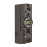
Figure 4 - The OutBack MX60 with PSDC Enclosure
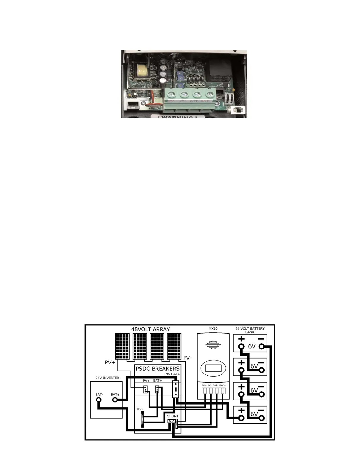
Figure 3 - MX60 wiring area and wiring terminals
6
The large terminal block in the center is for, (left to right), PV+, PV-, BAT- and BAT+. The aluminum box lug terminal on
the right side of the chassis is the equipment ground. The equipment-grounding terminal can be mounted on the outside
of the enclosure if desired, although normally the equipment-grounding conductors will be routed in the same conduits
with the input and output circuit conductors. If the equipment grounding terminal is moved to the outside, make sure that
the star washer is re-used. This washer is used to penetrate through the paint, thus grounding the chassis. The NEC
requires the use of an array disconnect and a battery disconnect. The MX60 can use a 60 amp 125VDC breaker such
as the OBDC60 breaker.
All of the large terminals should be torqued to 30 inch pounds. The PV /BAT terminal will accept up to 2AWG wire. The
equipment ground terminal also takes up to 2AWG wire.
An optional OutBack remote battery temperature sensor can be connected via the RJ11 “phone type” jack marked
"Battery Temp" to the right of the BAT+ terminal. This sensor is mounted on one of the batteries using the double back
tape included. Battery manufacturers recommended charging voltages are based on 77
o
F / 25
o
C. Your batteries will not
be properly charged using the manufacturer’s setpoints without a remote sensor unless the batteries remain at 77
o
F /
25
o
C. The OutBack Temp sensor will automatically change the setpoint voltages up or down depending on the battery’s
temperature. This is especially important in very cold or very hot climates. The battery temperature sensor is a highly
recommended option.
To the right of the temp sense jack is a small two position terminal block marked AUX. The terminals are marked Ground
and +12V. The terminals are programmable to accomplish an assortment of functions such as load diversion or alarms.
The output current available on this terminal block is 200 milliamps. This is enough to power the coil of a relay or for a
small piezo buzzer or LED indicator. The AUX output is protected internally by an automatic resetting poly-fuse device.
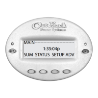
To the left of the PV+ terminal is an RJ45 jack marked MATE. The MATE is the OutBack remote display panel. Most of
the status that is available on the MX60 is available at the Mate as well. Some triggered events will be able to be
accomplished at the MATE also.
FIELD WIRING CONNECTIONS
The wiring terminals for the MX60 charge controller are shown in Figure 3. There is no required connection sequence.