The assembly procedure is reverse of the removal procedure, but the following instructions should be
observed:
(1) Be sure to align the match marks stamped on the Oval rotors, conrming their freely rotation.
(2) Make sure that all bolts, screws and nuts are tight in place.
(3) Using extra care not to distort shafts and associated gear coupled components, ensure that they are
correctly in mesh.
(4) Check the magnetic coupling for freely rotation.
(5) Potentiometer installation and adjustment
① As for the setting of resistance value, see
on page 8.
② When the potentiometer shaft is rotated counterclockwise as far as it will go, the resistance value
across terminals 2 and 3 is 100 ±10Ω. The resistance value increases with clockwise rotation.
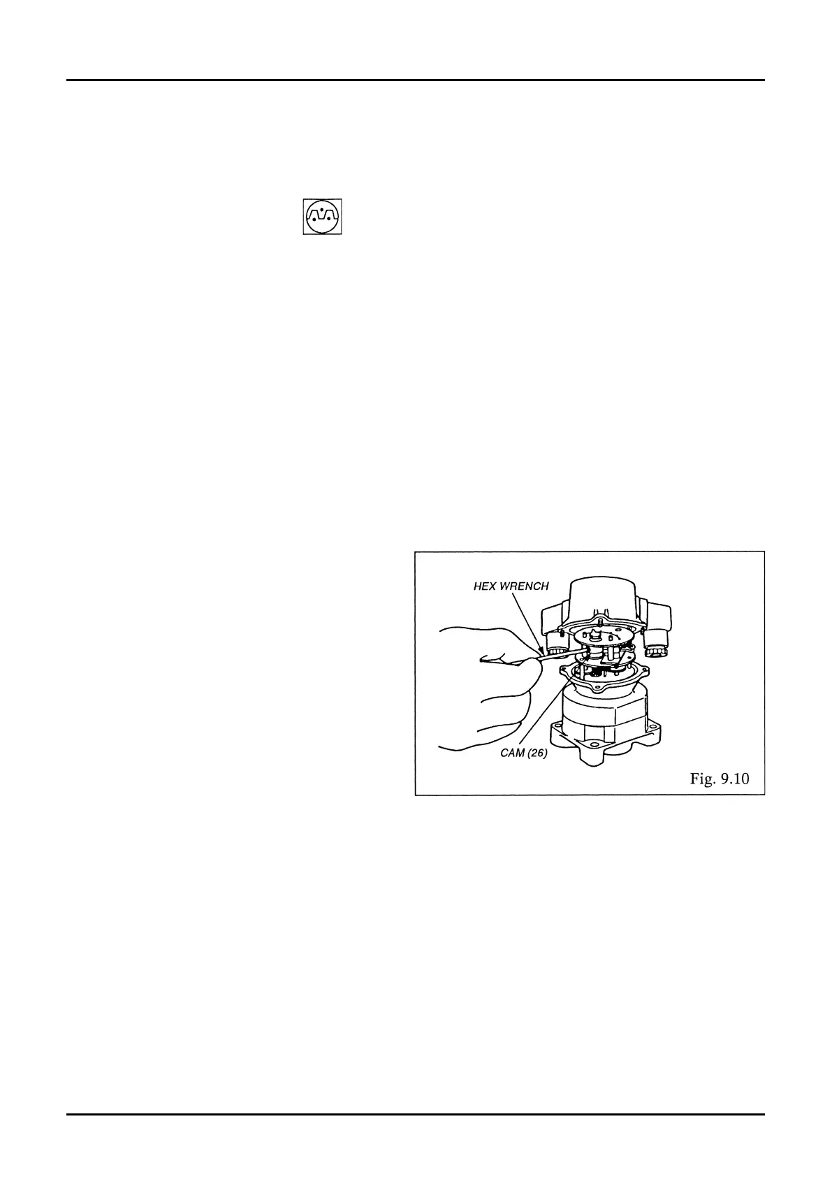
(6) Microswitch Adjustment
Actuating points on the dial scale are adjustable by loosening the cam (26) with hex wrench and adjusting
the rotational angle of the cam to the desired points according to
on page 8.
(SHUT side - upper cam; OPEN side - lower cam)