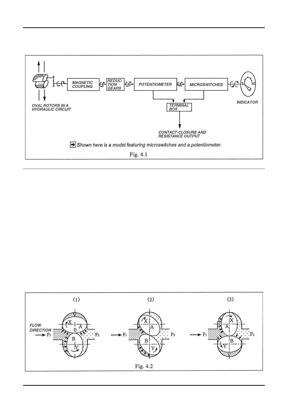
(1) Two Oval rotors are used in the wetted measuring chamber in contact with the fluid as shown in the
diagram below. Assume that the inlet pressure is P
1
and the outlet pressure P
2
. Pressure P
1
is uniformly
distributed over the entire teeth on its side P
1
; no torque acts on rotor B. Regarding rotor A, on the other
hand, pressures P
1
and P
2
act on its inlet tooth area (area “a”) and its outlet area (area “a”), respectively,
separated at a parting point “0” at which the two rotors mesh. Since their pressure relationship is P
1
>P
2
,
the resulting rotational dierential force represented by a・P
1
>a・P
2
acts on rotor A, forcing it to turn in the
arrow direction “X.” At a 90° displaced position, then, rotors A and B alternate places with each other; rotor
B is forced to turn in the arrow direction “Y.” This motion continues without coming across a dead point as
long as the process ow is maintained.
(2) Liquid is precisely quantied by a crescent-shaped cavity (V) formed by the chamber wall and Oval rotors.
The amount (q) of uid carried in every rotation of the Oval rotor is four times the crescent-shaped pocket
“V.”
(3) This turning eort of Oval rotors is transmitted to the indicator through a magnetic coupling, reduction
gear train, and potentiometer/microswitch arrangement. The volume of uid passing across the measuring
chamber is determined in this way, allowing the valve position to be displayed on the indicator.