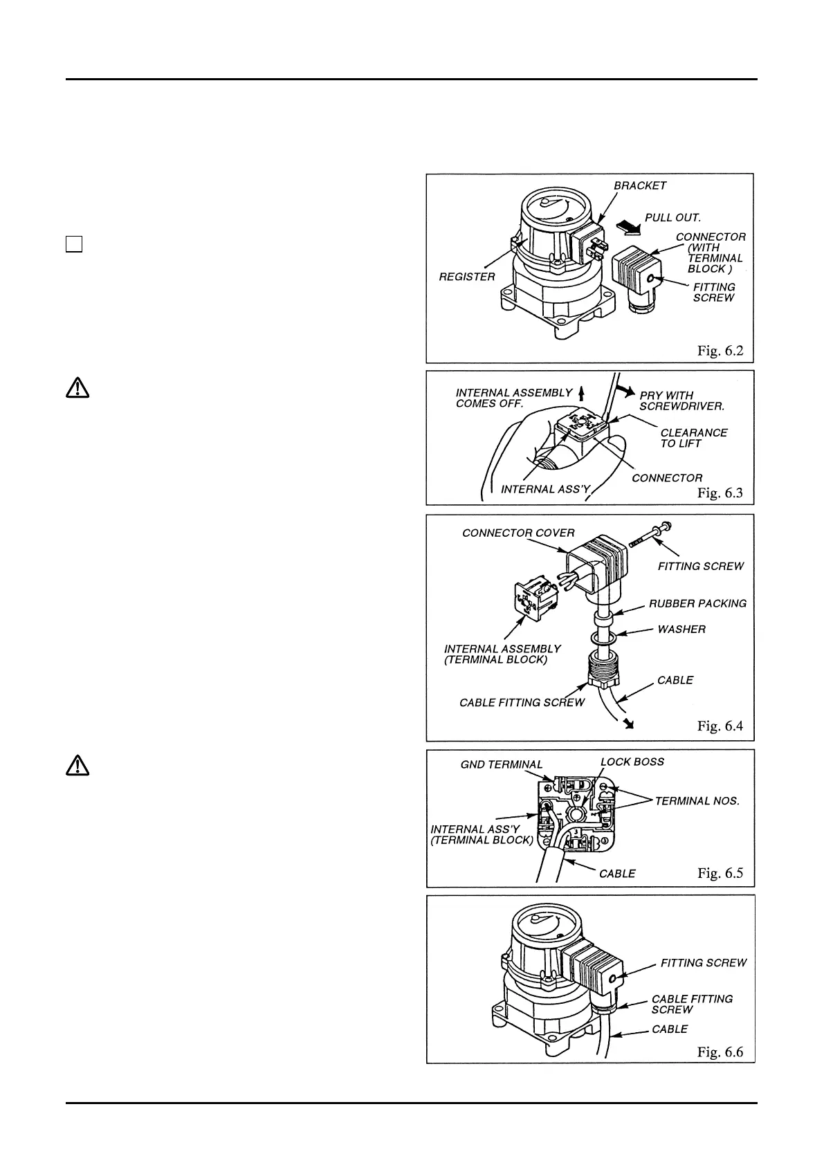
Remove the connector of the instrument and make connections of lead wires to its internal assembly (terminal
block).
(1) Using screwdriver, loosen the screw securing the
connector, extract the connector, and separate
from the bracket (Fig. 6.2).
NOTE: The bracket is coupled to the connector
with male/female connector.
(2) Holding the connector in your hand with its
internal assembly (terminal block) up, extract the
internal assembly by inserting the blade of
screwdriver into the lift clearance and prying o
as shown in Fig. 6.3.
(3) With connector tting screw, washer, and rubber
packing removed, pass them onto the cable, pass
the cable into the connector cover and pull it out
toward the terminal block. Rubber packing has
concentric cuts for adjustment: cut to the O.D. of
the cable used (Fig. 6.4).
(4) Separate three conductors of the cable, remove
insulation 7 mm approx. from individual
conductors, pass into respective screw slots on
the terminal block, and tighten with screw
securely (Fig. 6.5).
To ensure good electrical connections, we
recommend to tin lead wire ends.
(5) Install the wired terminal block into the
connector cover and secure it by forcing into
place until the lock boss of terminal block snaps
into position.
➡➡