① Check to see that the controller, such as the
valve, is operating properly. As long as the uid
is running, the nonuniform rotating sound of
Oval rotors should be heard. To make sure of it,
repeat opening and shutoff of the valve, or
other controller, several times.
② If nonuniform rotating sound is audible but the
pointer will not move (nor any electrical signal
output), trouble is suspected in the friction
clutch (13), reduction gear train (12), or
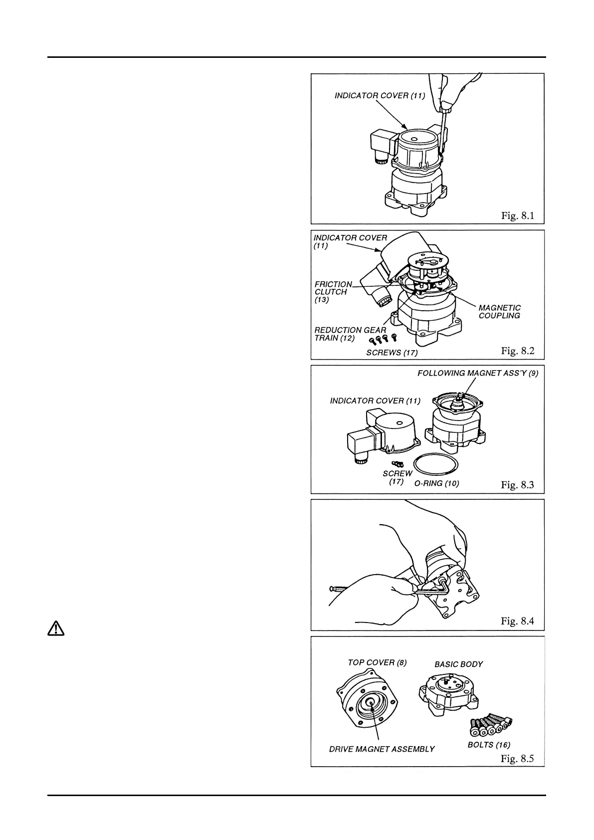
magnetic coupling (9). If this is the case, take o
four M3 screws (17) and remove the indicator
cover (11) (Fig. 8.1).
Allowing the hydraulic uid to ow in this state,
make sure to see that gears in the reduction
gear train (12) are moving (Fig. 8.2).
③ If, despite a hydraulic fluid flow, the reduction
gear train fails to move.
Taking off four M3 screws (17), remove the
indicator cover (11) and make sure of the
rotation of the following magnet assembly (9)
(Fig. 8.3).
If it is found all right, trouble is attributable to
the members in contact with the uid. If this is
the case, reduce the line pressure to zero.
④ Ensure that the hydraulic pressure has dropped
to zero and then remove the valve position
indicator from the hydraulic line.
⑤ Taking o six bolts (16), separate the top cover
(8) of basic body (Fig. 8.4).
⑥ Make sure of freely rotation of the driving
magnet assembly (5) (Fig. 8.5).
⇨Continued on next page.